
Diaphragm foam pump

a diaphragm and foam pump technology, applied in the direction of pump, positive displacement liquid engine, machine/engine, etc., can solve the problems of foam pump, fixed volume of foam generated by each pump, poor quality of foam,

Active Publication Date: 2012-05-08
GOJO IND INC
View PDF13 Cites 20 Cited by
  • Summary
  • Abstract
  • Description
  • Claims
  • Application Information

AI Technical Summary

Benefits of technology

The patent describes a diaphragm foam pump that uses a flexible material to create a vacuum that causes foamable liquid and air to flow into the mixing chamber and be forced out as foam. The pump includes an electric motor and a motor-driven element that repeatedly expands and contracts the diaphragm. The technical effect of this invention is a more efficient and effective foam pump that can create consistent and high-quality foam.

Problems solved by technology

The more minute and numerous the air bubbles the thicker and softer the foam, although too much or too little air can cause the foam to be of poor quality.
Many existing foam pump designs employ a piston type mechanism, which results in a fixed volume of foam generated by each activation of the foam pump, without any ability to adjust.

Method used


Image

  • Diaphragm foam pump
  • Diaphragm foam pump
  • Diaphragm foam pump

Examples


Embodiment Construction

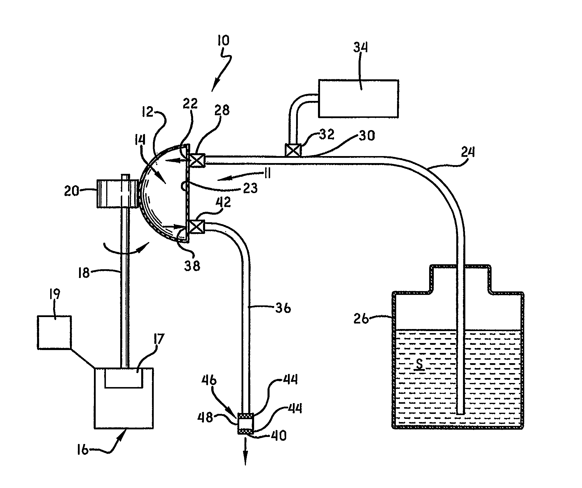
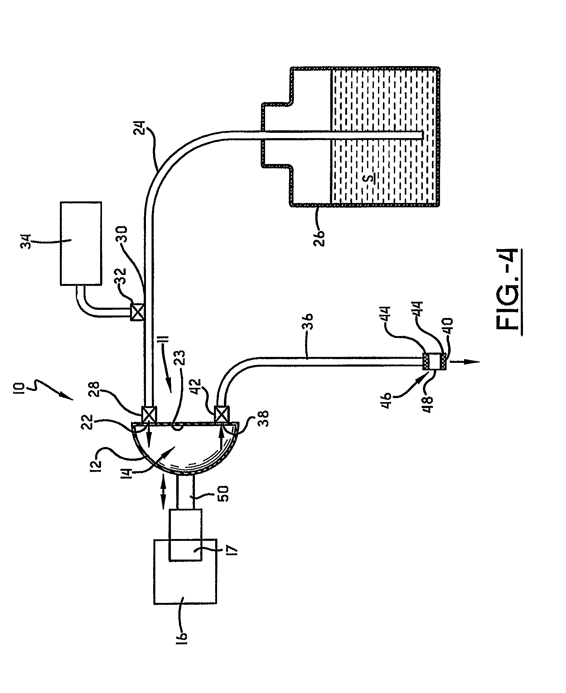
[0009]A dispenser according to the concepts of the present invention is shown in FIG. 1 and is indicated generally by the numeral 10. Dispenser 10 includes a foam pump 11 having a diaphragm 12 that is generally dome shaped. Diaphragm 12 is made of a flexible and resilient material that collapses upon the introduction of an external force, and then returns to its original shape when the force is removed. Suitable materials include, for example, silicone, thermoplastic elastomers, and the like. Diaphragm 12 defines an internal mixing chamber 14 therein, as will be discussed in greater detail below. Diaphragm 12 may be mounted in a dispenser housing (not shown) that provides a mounting mechanism, as well as a means for securing other components of dispenser 10.

[0010]Dispenser 10 also includes an electric motor 16 having a rotating motor shaft 18. Electric motor 16 may be any known electric motor having a rotating shaft, including, for example, a DC motor provided with a battery power s...


PUM


Abstract

A foam pump including a diaphragm made of a flexible material defining a mixing chamber and having an inlet and an outlet. An inlet passageway, having a one-way valve therein, is in fluid communication with a reservoir containing a foamable liquid and the inlet. The inlet passageway includes an air inlet and associated one-way valve. The pump includes an outlet passageway, having a one-way valve therein, in fluid communication with the outlet. The foam pump includes an electric motor. that drives a motor driven element to collapse and expand the diaphragm. Expansion of the diaphragm creates a vacuum causing foamable liquid and air to flow into the mixing chamber. Collapsing of the diaphragm causes the liquid and air mixture to be forced out as foam.

Description

FIELD OF THE INVENTION[0001]The invention herein resides in the art of foam pumps, wherein a foamable liquid and air are mixed to generate a foam product. More particularly, the invention relates to diaphragm foam pumps wherein a diaphragm is caused to repeatedly collapse and expand by a motor driven element, thereby alternately drawing foamable liquid and air into a mixing chamber within the diaphragm and forcing the mixture out as a foam product.BACKGROUND OF THE INVENTION[0002]For many years, it has been known to dispense liquids, such as soaps, sanitizers, cleansers, disinfectants, and the like from a dispenser housing maintaining a refill unit that holds the liquid and provides the pump mechanisms for dispensing the liquid. The pump mechanism employed with such dispensers has typically been a liquid pump, simply dispensing a predetermined quantity of the liquid upon movement of an actuator. Recently, for purposes of effectiveness and economy, it has become desirable to dispense...

Claims


Application Information

Patent Timeline
Patent Type & Authority Patents(United States)
IPC IPC(8): F04B17/00
CPCA47K5/1208A47K5/16B05B7/0037B05B7/0062B05B7/262F04B19/06F04B13/00
Inventor REYNOLDS, AARON R.
Owner GOJO IND INC
Learn More