
Zoom lens and image pickup apparatus having the same

a pickup apparatus and zoom lens technology, applied in the direction of projectors, instruments, printers, etc., can solve the problems of difficult to correct various kinds of aberrations, the effective diameter the whole of the lens system cannot be sufficiently shortened, so as to achieve wide field angle, high zoom ratio, and high optical performance.

Inactive Publication Date: 2012-05-01
CANON KK
View PDF9 Cites 3 Cited by
  • Summary
  • Abstract
  • Description
  • Claims
  • Application Information

AI Technical Summary

Benefits of technology

The present invention provides a zoom lens with a small-sized optical system, a wide field angle, and a high zoom ratio that maintains high optical performance throughout the entire zoom range. The zoom lens comprises a first lens unit with positive refractive power, a second lens unit with negative refractive power, a third lens unit with positive refractive power, and a rear group including at least one lens unit. Each lens unit moves to perform the zoom operation, and certain conditions are met to achieve the desired zoom effect. The zoom lens is suitable for use in an image pickup apparatus.

Problems solved by technology

In particular, a lens effective diameter increases and a whole of the lens system cannot be sufficiently shortened.
At the same time, it is difficult to correct various kinds of aberrations such as a chromatic aberration at a telephoto end.
Further, in accordance with the increase of the zoom ratio, an error which is caused by a tilt or a decentering in assembling a lens or a lens unit increases.
When the sensitivity of the decentering of the lens or the lens unit is large, the optical performance is greatly deteriorated by the decentering or the optical performance is greatly deteriorated in an anti-shake operation.
If these configurations are not appropriately set, it is difficult to reduce the size of the whole system and to obtain a zoom lens which has a wide field angle and a high zoom ratio and also has a high optical performance.

Method used


Image

  • Zoom lens and image pickup apparatus having the same
  • Zoom lens and image pickup apparatus having the same
  • Zoom lens and image pickup apparatus having the same

Examples


Embodiment Construction

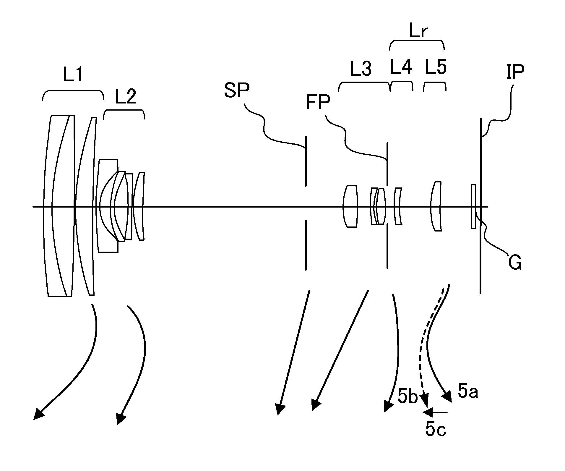
[0027]Exemplary embodiments of a zoom lens and an image pickup apparatus having the zoom lens of the present invention will be described below with reference to the accompanied drawings. The zoom lens of the present invention includes a first lens unit having a positive refractive power, a second lens unit having a negative refractive power, a third lens unit having a positive refractive power, and a rear group containing at least one lens unit, in order from an object side to an image side. The zoom lens moves the lens units so that a total lens length at a telephoto end is longer than that at a wide-angle end to perform a zoom operation.

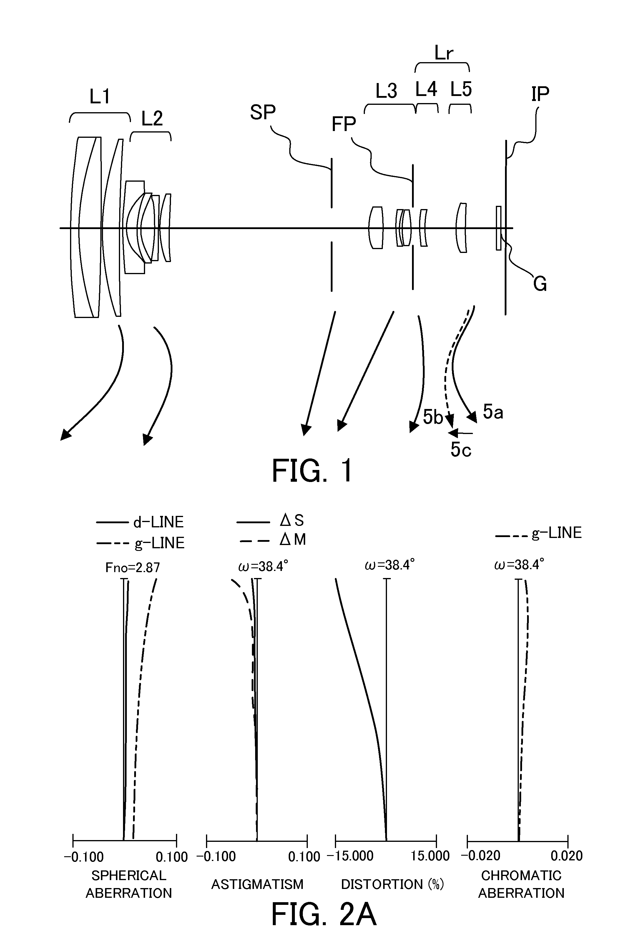
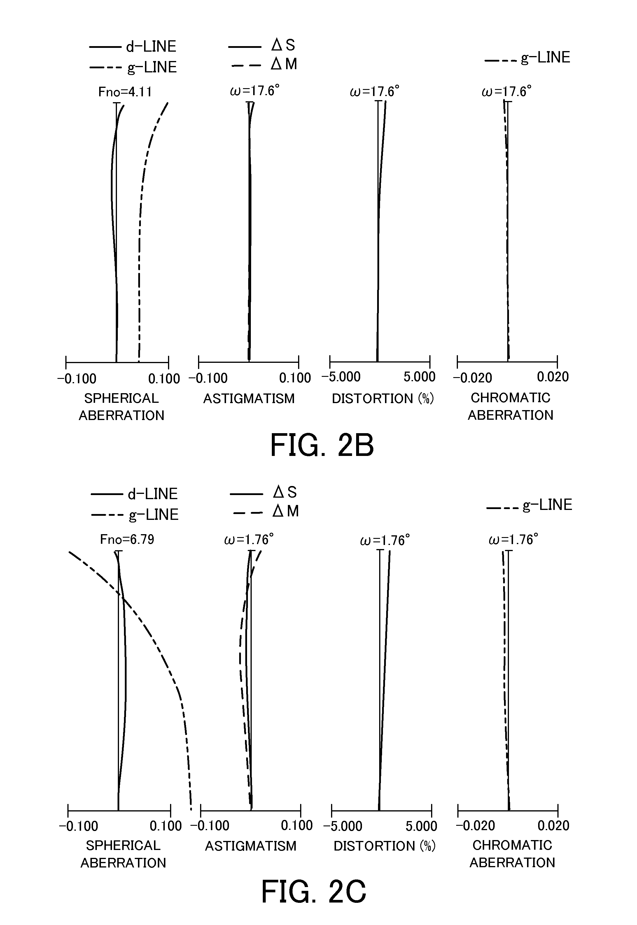
[0028]FIG. 1 is a cross-sectional diagram of a zoom lens at a wide-angle end (a short focal length end) in Embodiment 1 of the present invention. FIGS. 2A to 2c are aberration diagrams of a zoom lens at a wide-angle end, at an intermediate zoom position, and at a telephoto end (a long focal length end), respectively, in Embodiment 1 of the present ...


PUM


Abstract

A zoom lens comprises a first lens unit having a positive refractive power, a second lens unit having a negative refractive power, a third lens unit having a positive refractive power, and a rear group including at least one lens unit, in order from an object side to an image side. Each of the lens units is configured to move so that a total lens length at a wide-angle end is longer than that at a telephoto end to perform a zoom operation. A movement amount M1 of the first lens unit at the wide-angle end and the telephoto end with respect to an imaging surface, a focal length f1 of the first lens unit, and focal lengths fw and ft of a whole system at the wide-angle end and the telephoto end are appropriately set.

Description

BACKGROUND OF THE INVENTION[0001]1. Field of the Invention[0002]The present invention relates to a zoom lens and an image pickup apparatus having the same, and more particularly relates to an image pickup apparatus using a solid-state image pickup element such as a video camera, an electronic still camera, a broadcasting camera, or a monitoring camera, or an image pickup apparatus using a silver salt film.[0003]2. Description of the Related Art[0004]An image pickup optical system used for an image pickup apparatus needs to be a zoom lens which has a short total lens length, a small size, a high zoom ratio, and a high resolution.[0005]Commonly, in order to maintain a predetermined zoom ratio and also to reduce the size of a whole system, the refractive power of each lens unit constituting the zoom lens needs to be strengthened and also the number of the lenses needs to be reduced. However, in such a zoom lens, the thickness of the lens increases in order to ensure an edge thickness i...

Claims


Application Information

Patent Timeline
Patent Type & Authority Patents(United States)
IPC IPC(8): G02B15/14
CPCG03B5/00G02B15/173G02B15/144113G02B15/145121G02B15/145129
Inventor FUJISAKI, TOYOKATSU
Owner CANON KK
Learn More