
Introducer sheath

a technology of introducer sheath and inserter, which is applied in the field of introducer sheath, can solve the problems of low frictional force of the seal provided within the range difficulty in insertion and withdrawal of such implements into and out of the introducer sheath, and inability to achieve hemostasis

Active Publication Date: 2012-03-20
MEDTRONIC VASCULAR INC
View PDF24 Cites 34 Cited by
  • Summary
  • Abstract
  • Description
  • Claims
  • Application Information

AI Technical Summary

Benefits of technology

The present invention provides an introducer sheath with a valve that can provide a hemostatic seal with a guide wire and various surgical implements and medical devices. The valve has a front seal, a first intermediate seal, and a second intermediate seal, which support and center the guide wire and allow the surgical implement or medical device to pass through. A rear seal is also included to provide a hemostatic seal with different sizes of surgical implements and medical devices. The valve is designed to prevent blood leakage and to create hemostasis when no guide wire, surgical implement, or medical device is present. The introducer sheath with the valve provides a versatile and effective tool for medical procedures.

Problems solved by technology

While these structures have met with varying degrees of success and acceptance, they generally have suffered from a common disadvantage: sealing bodies (whether passive or active) that provide an effective hemostatic seal with a guide wire and with a wide range of cross-sectional diameters of surgical implements and medical devices.
Passive valve structures tend to impose substantial frictional forces on at least some sizes of traversing implements, e.g., the larger sizes, thereby making is difficult for the user to insert and withdraw such implements into and out of the introducer sheath.
While these simple sealing devices accommodate only a very narrow range of surgical implement diameters, the seals provided within that range tend to impose frictional forces that are low.
In many cases, hemostasis cannot be achieved due to inadequate sealing, and many introducer sheaths leak when only a guide wire is placed in the introducer sheath.

Method used


Image

  • Introducer sheath
  • Introducer sheath
  • Introducer sheath

Examples


Embodiment Construction

[0027]The following detailed description is merely exemplary in nature and is not intended to limit the invention or the application and use of the invention. There is no intention to be bound by any expressed or implied theory presented in the preceding technical field, background, brief summary or the following detailed description.

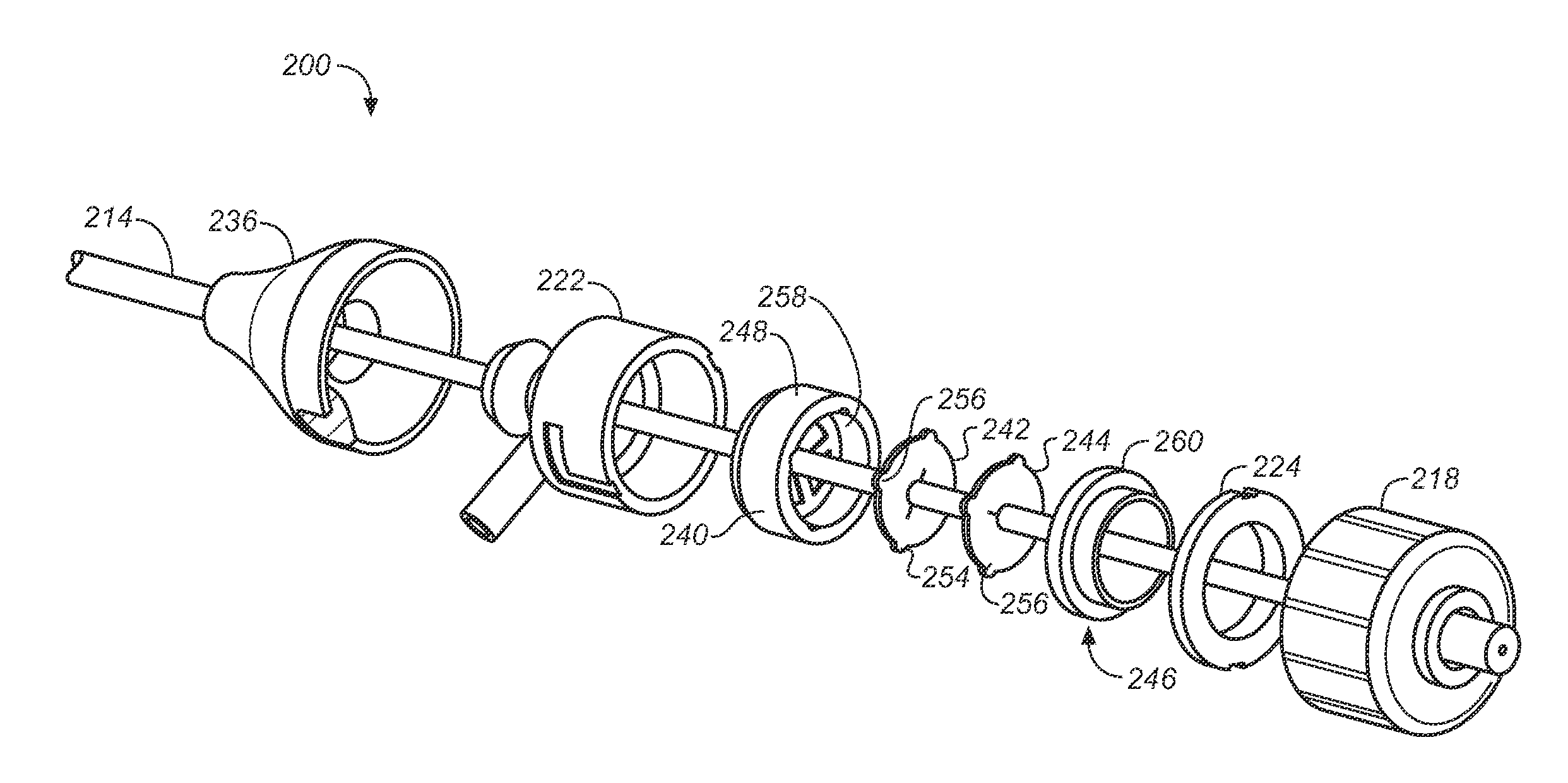
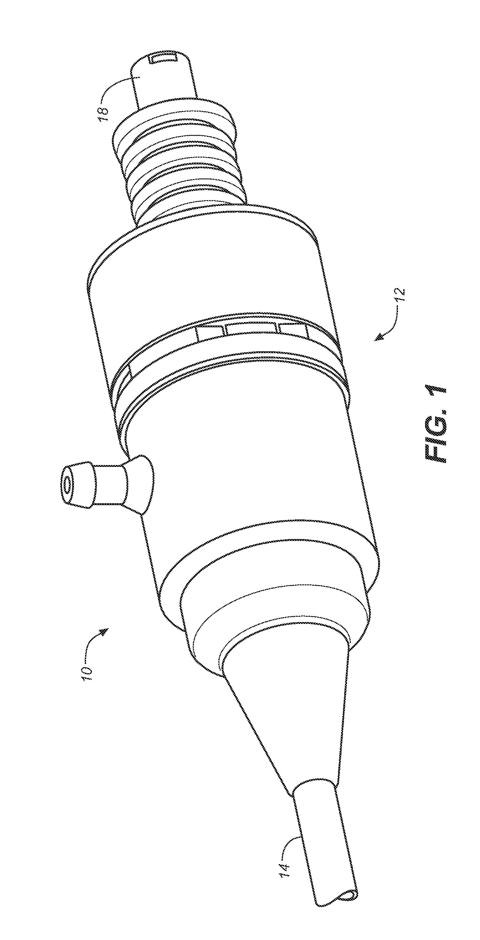
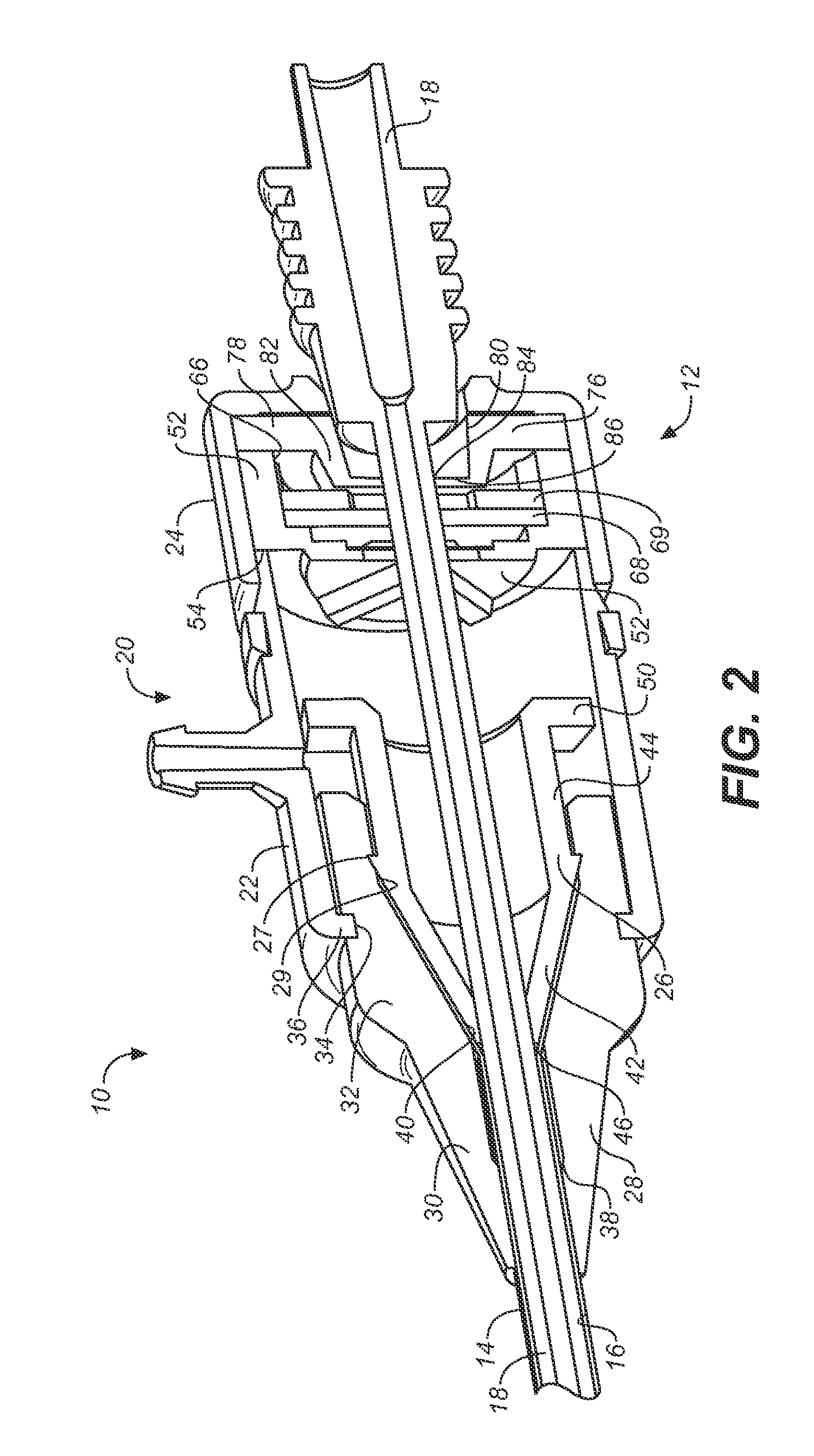
[0028]FIGS. 1 and 2 schematically illustrate an introducer sheath 10 according to an embodiment of the invention. As illustrated, the introducer sheath 10 includes a hemostatic valve 12, and an elongated sheath 14 that extends from one end of the valve 12. The sheath 14 is a substantially cylindrical and elongated hollow member that is configured to be inserted into a body lumen through which blood flows, such as a blood vessel, as discussed in further detail below. An interior lumen 16 (see FIG. 2) of the sheath 14 is sized and configured to receive, for example, a dilator 18, although any suitably sized surgical implement or medical device that is to ...


PUM


Abstract

An introducer sheath includes a elongated sheath configured to be inserted into a blood vessel. The elongated sheath includes a central lumen configured to allow a surgical implement or medical device to pass therethrough. The introducer sheath also includes a hemostatic valve operatively connected to the sheath. The hemostatic valve is configured to prevent blood in the blood vessel from exiting the introducer sheath assembly when the elongated sheath is located in the blood vessel. The hemostatic valve includes a plurality of seals supported by a housing, including a front seal configured to provide a hemostatic seal with a guide wire, and a rear seal configured to provide a hemostatic seal with a range of sizes of implements and devices. The housing is configured to provide strain recovery for strain induced by displacement forces generated during movement of the implement or medical device through the plurality of seals.

Description

BACKGROUND[0001]1. Field of the Invention[0002]The present invention is directed to an introducer sheath having a hemostatic valve that can maintain hemostasis around surgical implements and medical devices having a wide variety of cross-sectional diameters during surgical procedures.[0003]2. Background of the Invention[0004]Introducer sheaths are used to assist in the introduction of guide wires, surgical implements, and medical devices into a patient's vascular system (typically an artery) for many different types of intravascular procedures. The introducer sheath and its associated dilator are designed to penetrate the skin and wall of the blood vessel and be positioned within the blood vessel so that surgical implements and medical devices may be advanced and withdrawn through the introducer sheath. In this way, even when multiple surgical implements and / or medical devices are used in a single procedure, there is a single placement of the introducer sheath through the skin and v...

Claims


Application Information

Patent Timeline
Patent Type & Authority Patents(United States)
IPC IPC(8): A61M5/178
CPCA61M25/0097A61M25/0662A61M39/0606A61M2039/0653A61M2039/0626A61M2039/064A61M2039/062
Inventor ARGENTINE, JEFFERY
Owner MEDTRONIC VASCULAR INC
Learn More