
Active on-patient sensor, method and system

a sensor and patient technology, applied in the field of sensing conditions, can solve the problem of not being able to expect all aspects of the ahrq guidelines to be followed for all

Active Publication Date: 2012-02-07
ORTHOCARE INNOVATIONS LLC
View PDF56 Cites 116 Cited by
  • Summary
  • Abstract
  • Description
  • Claims
  • Application Information

AI Technical Summary

Benefits of technology

[0012]The present invention provides apparatus to sense a condition adjacent a human body, comprising: a sensor to sense a condition (including pressure from body weight and moisture from incontinence, for example) adjacent a human body; a signal processing circuit to which the sensor connects; a transmitter connected to the signal processing circuit; a power supply connected to provide electricity for operation of the sensor, the signal processing circuit, and the transmitter; and a flexible printed circuit substrate having at least the signal processing circuit, the transmitter, and the power supply mounted thereon in low profile enabling disposition of the apparatus adjacent a human body. In some embodiments the sensor is detachable. The sensor can be single-mode or multiple-mode, such as one that responds to both pressure and moisture.
[0017]The present invention also provides a method of monitoring a patient, comprising: connecting a condition sensing apparatus to a patient, including performing at least one from the group consisting of adhering a flexible substrate of the condition sensing apparatus to skin of the patient and putting diapers having the flexible substrate on the patient, the flexible substrate having a sensor, a transmitter and a battery connected thereto; collecting data transmitted from the condition sensing apparatus when the condition sensing apparatus senses a pressure or incontinence condition adjacent the patient; and replacing the sensor of the condition sensing apparatus, including disconnecting the sensor from the condition sensing apparatus and connecting a replacement sensor thereto such that the flexible substrate, the transmitter and the battery are reused. Other steps that can be included in the foregoing or other definitions of the present invention include one or more (that is, they can be used individually or in combinations) of the following: transmitting from the condition sensing apparatus such that signal collision with transmissions from other condition sensing apparatus on the patient is avoided; using the collected data to generate care protocol scheduling for the patient; maintaining and updating remote from the condition sensing apparatus data identifying the condition sensing apparatus; transmitting data from the condition sensing apparatus to a bedside monitor and locally transferring data from the bedside monitor to a data collection unit; receiving through any of a plurality of diversity antennas a transmission from the condition sensing apparatus; detecting in-range and out-of-range transmission conditions relative to the condition sensing apparatus; and sending, in response to the collected data, a control signal through the operation of which the patient is notified of the pressure or incontinence condition.

Problems solved by technology

However, with staff / patient ratios typically found in nursing homes, it may be impractical to expect all aspects of the AHRQ guidelines to be followed for all but high-risk patients.

Method used


Image

  • Active on-patient sensor, method and system
  • Active on-patient sensor, method and system
  • Active on-patient sensor, method and system

Examples


Embodiment Construction

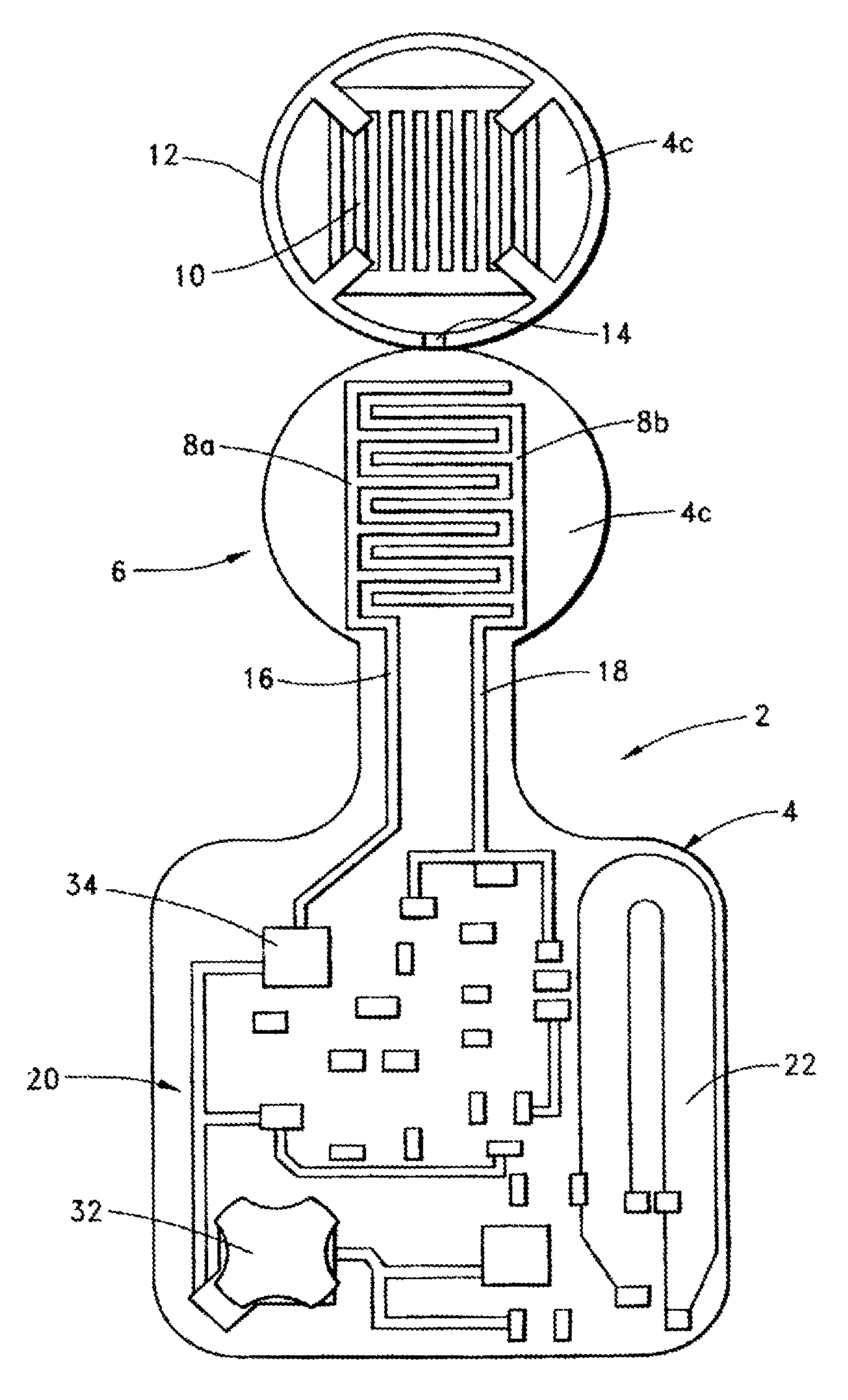
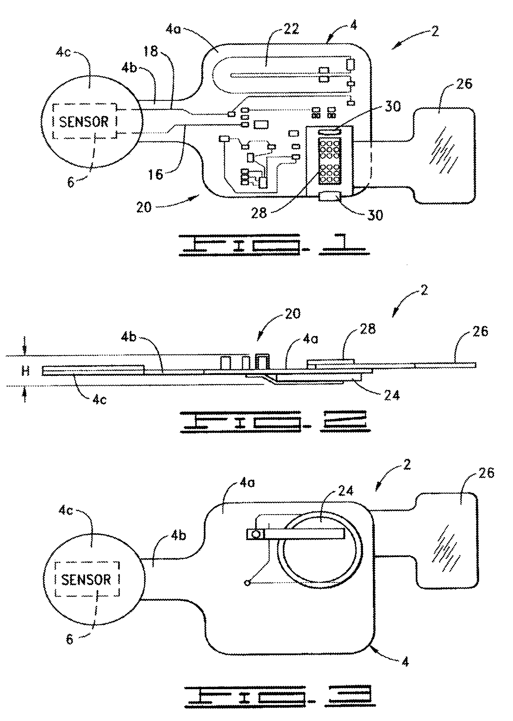
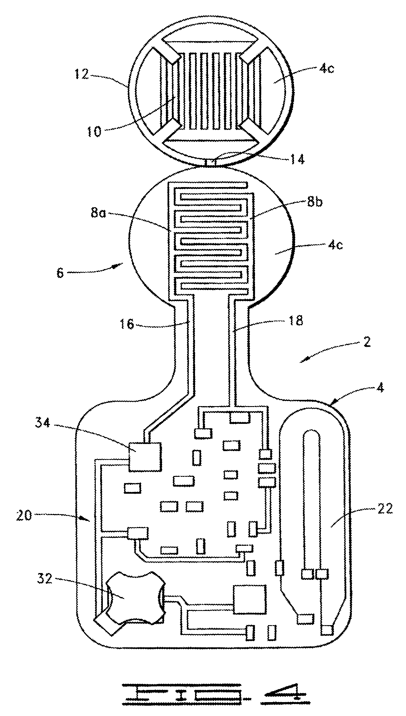
[0035]An implementation of an apparatus 2 to sense a condition adjacent a human body in accordance with the present invention is illustrated in FIGS. 1-3. This sensing apparatus 2 is preferably an active device in the sense that it contains its own internal power supply. This embodiment is, and other embodiments desirably are, low profile and flexible to conform to the exterior of human body. Such low profile refers to the thinness exhibited in FIG. 3 as dimension “H”. In general, the sensing apparatus 2 can be implemented using analog or digital electronics technology (including a combination of both).

[0036]The illustrated embodiment of FIGS. 1-3 includes a flexible printed circuit substrate 4 having other components described below mounted on it in a manner to obtain the low profile (small “H”) characteristic of the invention, which is one feature enabling disposition of the apparatus 2 adjacent a human body. Such disposition can be in any suitable manner, including directly to a ...


PUM


Abstract

A sensor (which could be detachable) to sense a condition (including pressure from body weight or moisture from incontinence; applied by adhering to skin of a human body or by putting a diaper on the human body, for example), a signal processing circuit, a periodic or continuous transmitter, and a power supply (typically including a battery) are associated with a flexible substrate in low profile enabling disposition adjacent the human body. A transmitter antenna is on the substrate. Insulator film between battery contacts and a switch-and-transistor combination are two power-on techniques. A bedside monitor, a transceiver configured to receive signals from and transmit signals to the bedside monitor, and a computer connected with the transceiver can be included. Other features include: notification signaling; differently responsive antennas; unique identification; low battery detection; anti-collision transmission; patient protocol scheduling; local data transfer from the bedside monitor; and out-of-range transmission detection.

Description

CROSS-REFERENCE TO RELATED APPLICATION[0001]This application is a continuation of application Ser. No. 10 / 263,380, filed Oct. 2, 2002, which is incorporated by reference herein.BACKGROUND OF THE INVENTION[0002]This invention relates generally to sensing conditions related to a human body and more particularly to sensing conditions that pertain to the care or well-being of a person who is confined to a bed or other sedentary position or who is incontinent. It also relates to providing notification in response to such sensing, which notification can be sent to the person whose conditions are being sensed or to others such as health care providers, for example. Two specific applications of the present invention that can be used separately or together relate to a medical sensor and a system and method of monitoring (1) one or more pressure sensitive areas of a human body and (2) dry / wet conditions adjacent a human body.[0003]Although aspects of the present invention have application wit...

Claims


Application Information

Patent Timeline
Patent Type & Authority Patents(United States)
IPC IPC(8): G08B23/00
CPCA61B5/1113A61B5/445A61B5/447G08B21/0461G08B21/22A61B5/002A61B2560/0214H05K1/189A61B5/0022A61B5/6808A61B2560/0412A61B2562/043A61B2562/164A61B2562/166
Inventor ORTEGA, GIOVANI M.SCIARRA, MICHAEL J.
Owner ORTHOCARE INNOVATIONS LLC
Learn More