Dielectric barrier discharge lamp
a technology of dielectric barrier and discharge lamp, which is applied in the direction of gas discharge lamp details, electric discharge tubes, electrical apparatus, etc., can solve the problems of low life time, inconvenient replacement of existing lamps, and inability to meet the needs of external cooling, etc., and achieve the effect of facilitating the replacement of existing lamps
- Summary
- Abstract
- Description
- Claims
- Application Information
AI Technical Summary
Benefits of technology
Problems solved by technology
Method used
Image
Examples
first embodiment
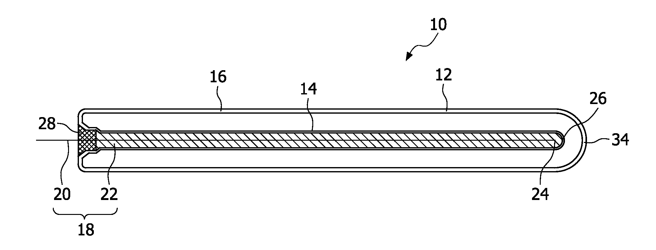
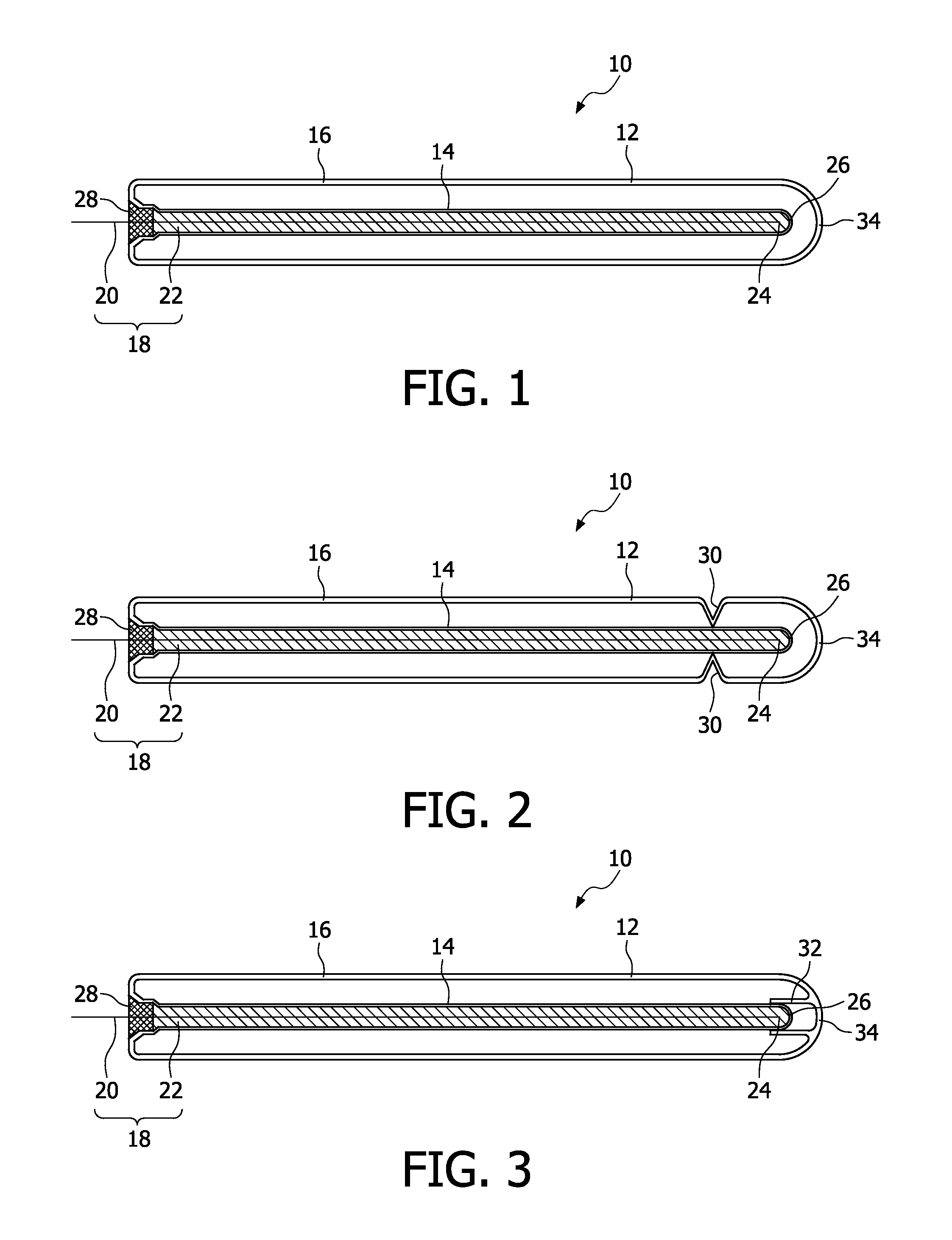
[0023]In the in FIG. 1 illustrated first embodiment of the dielectric barrier discharge lamp 10 according to the invention the dielectric barrier discharge lamp 10 comprises an outer tube 12 and an inner tube 14 arranged coaxial to the outer tube 12. The dielectric barrier discharge lamp 10 comprises an outer electrode 16, which may be a conductive coating or preferably a conductive meshed web. The outer electrode 16 may be arranged on the outside or the inside of the outer tube 12.
[0024]The inner tube 14 comprises an inner electrode 18 consisting of a conductor 20 and a conductive granulated material 22, wherein the inner tube 14 is only partially filled by the conductor 20 and the granulated material 22. For sake of clarity the specific particles of the granulated material and the partial filling of the inner tube 14 are not illustrated in detail. Due to the partial filling of the inner tube 14 by the conductive granulated material 22 an electrical contact between the conductor 20...
second embodiment
[0027]In the dielectric barrier discharge lamp 10 illustrated in FIG. 2 the outer tube 12 comprises grooves 30, by which the inner tube 14 may be at least partially supported. Due to the chosen design of the grooves 30 a vibration or swinging of the inner tube 14 may be prevented leading to an increased mechanical stability of the inner tube 14.
third embodiment
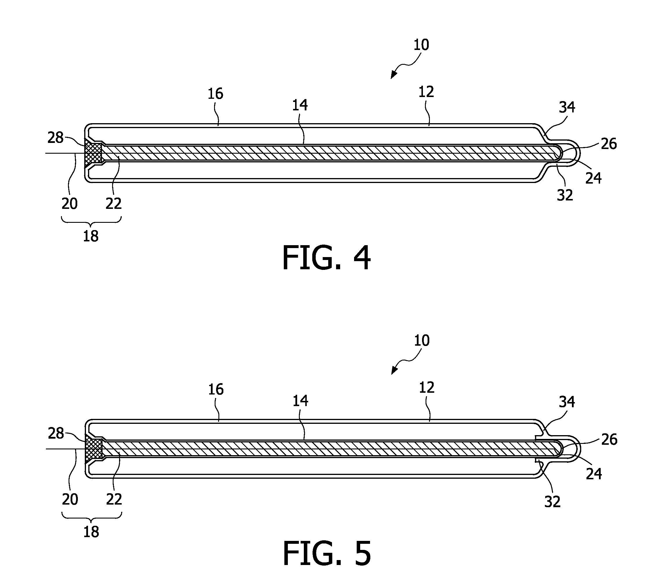
[0028]In the dielectric barrier discharge lamp 10 illustrated in FIG. 3 the increased mechanical stability of the inner tube 14 is provided by a mainly tubular protrusion 32 at a distal front face 34 of the outer tube 12. Between the distal end 26 of the inner electrode 14 and the protrusion 32 is at least a clearance fit or a greater gap provided allowing a thermal expansion of the inner tube 14 in radial direction.
PUM
 Abstract
Description
Claims
Application Information
 - R&D
- Intellectual Property
- Life Sciences
- Materials
- Tech Scout
- Unparalleled Data Quality
- Higher Quality Content
- 60% Fewer Hallucinations
Browse by: Latest US Patents, China's latest patents, Technical Efficacy Thesaurus, Application Domain, Technology Topic, Popular Technical Reports.
© 2025 PatSnap. All rights reserved.Legal|Privacy policy|Modern Slavery Act Transparency Statement|Sitemap|About US| Contact US: help@patsnap.com


