
Sheet stopping structure

a technology of stopping structure and sheet, applied in the direction of thin material processing, article separation, transportation and packaging, etc., can solve the problems of multi-feeding problem, unusable conventional sheet stopping structure b>1/b>, etc., to reduce layout space and minimize the possibility of losing effectiveness through self-deformation

Inactive Publication Date: 2012-01-17
PRIMAX ELECTRONICS LTD
View PDF5 Cites 5 Cited by
  • Summary
  • Abstract
  • Description
  • Claims
  • Application Information

AI Technical Summary

Benefits of technology

The present invention introduces an improved system for preventing sheets from moving too far during use. This new design reduces the likelihood that it will become less effective due to its own deformation or take up more room than necessary.

Problems solved by technology

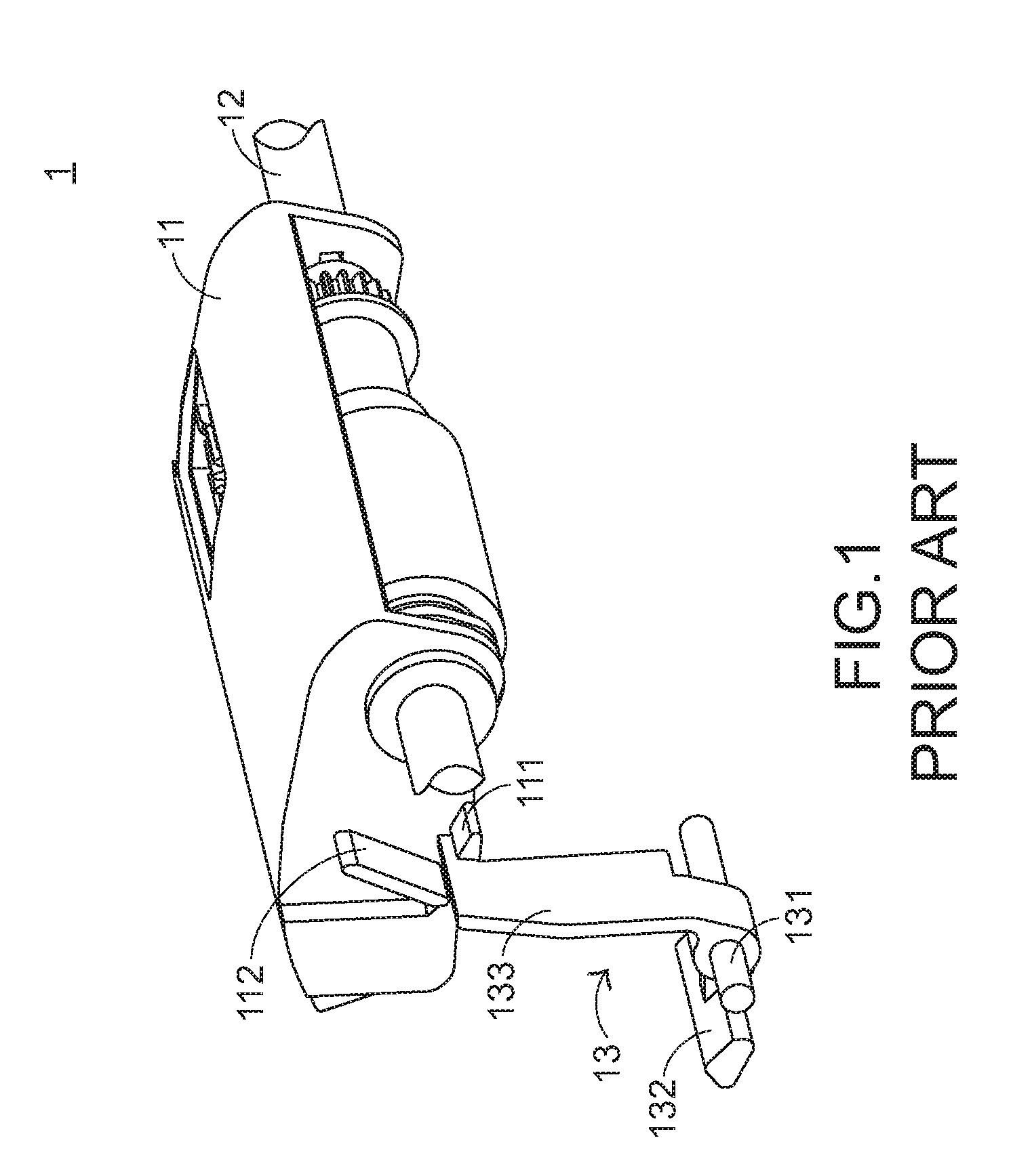
The technical problem addressed in this patent text is the deformation of the sheet stopper in the conventional sheet stopping structure used in office machines, which can lead to a loss of the sheet stopping function and potential multi-feeding issues. There is a need for an improved sheet stopping structure to overcome these drawbacks.

Method used


Image

  • Sheet stopping structure
  • Sheet stopping structure
  • Sheet stopping structure

Examples


Embodiment Construction

[0030]The present invention provides a sheet stopping structure. The sheet stopping structure may be applied to an office machine for feeding paper sheets.

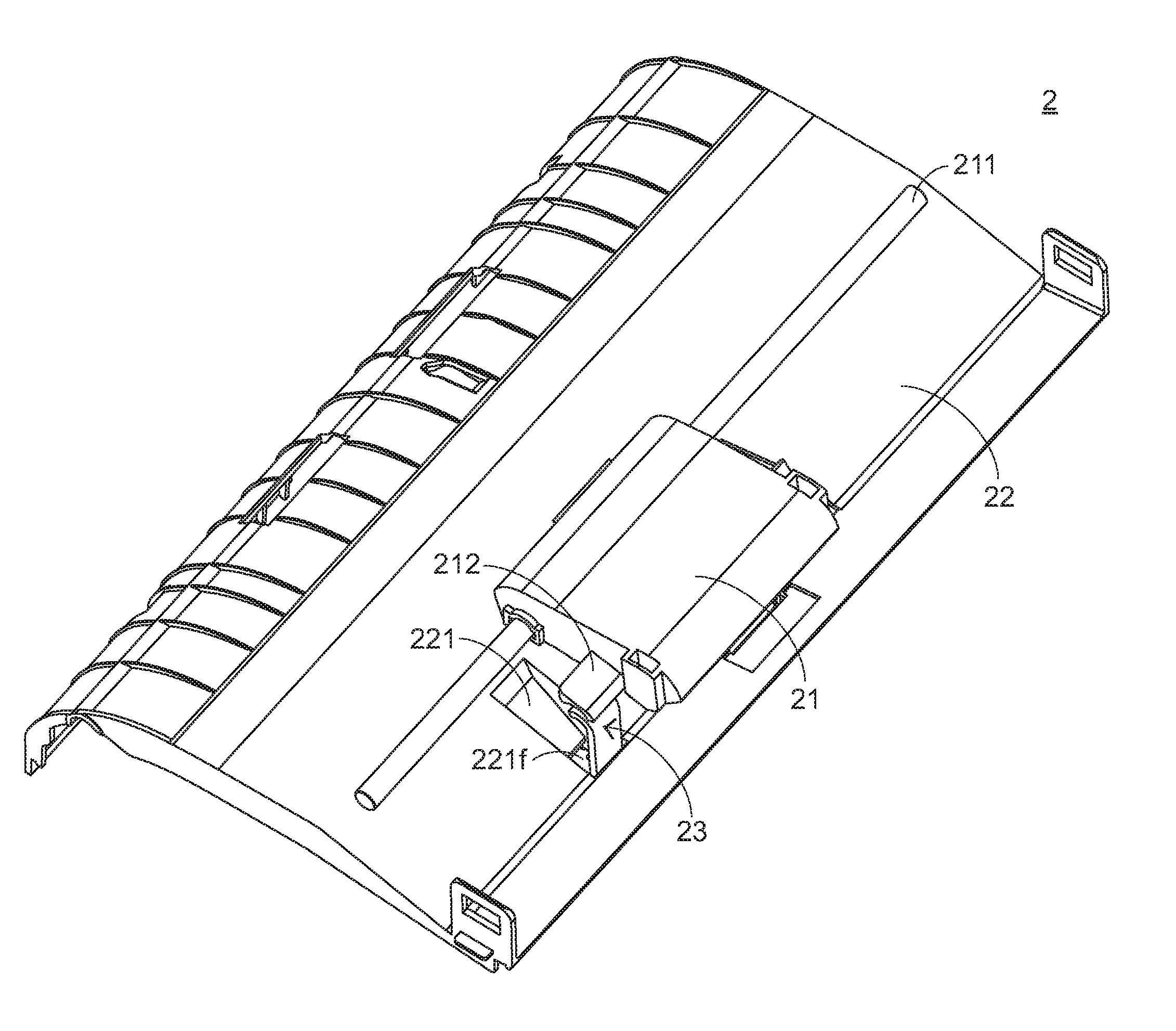
[0031]FIG. 3A is a schematic perspective view illustrating a sheet stopping structure according to an embodiment of the present invention. FIG. 3B is a schematic cutaway view illustrating the sheet stopping structure of FIG. 3A. As shown in FIGS. 3A and 3B, the sheet stopping structure 2 comprises a sheet pick-up arm 21, a sheet guide casing 22 and a sheet stopper 23.

[0032]FIG. 4A is a schematic top view illustrating the front side of the sheet guide casing 22 of the sheet stopping structure according to an embodiment of the present invention. FIG. 4B is a schematic rear view illustrating the rear side of the sheet guide casing 22 of the sheet stopping structure according to an embodiment of the present invention. Please refer to FIGS. 4A and 4B. The sheet pick-up arm 21 comprises a rotating shaft 211 and a protruding block 212. T...


PUM


Abstract

A sheet stopping structure includes a sheet pick-up arm, a sheet guide casing and a sheet stopper. A receiving recess is formed in the sheet guide casing. Two sliding slots are respectively formed in two sidewalls of the receiving recess. The sheet stopper is installed in the receiving recess, and movable along the two sliding slots. When the sheet pick-up arm is in a standby position, the sheet stopper is maintained in an upright status and protruded outside the surface of the sheet guide casing. When the sheet pick-up arm is lowered to a sheet pick-up position, the sheet stopper is rotated and then stopped down within the receiving recess.

Description


Claims


Application Information

Patent Timeline
Owner PRIMAX ELECTRONICS LTD
Learn More