
Programmable camera control unit with updatable program

a camera control and program technology, applied in the field of camera control units, can solve the problems of control unit hardware, difficult to configure to communicate with the many different types of cameras in the market, and differences among ccds

Inactive Publication Date: 2012-01-03
KARL STORZ IMAGING INC
View PDF41 Cites 936 Cited by
  • Summary
  • Abstract
  • Description
  • Claims
  • Application Information

AI Technical Summary

Benefits of technology

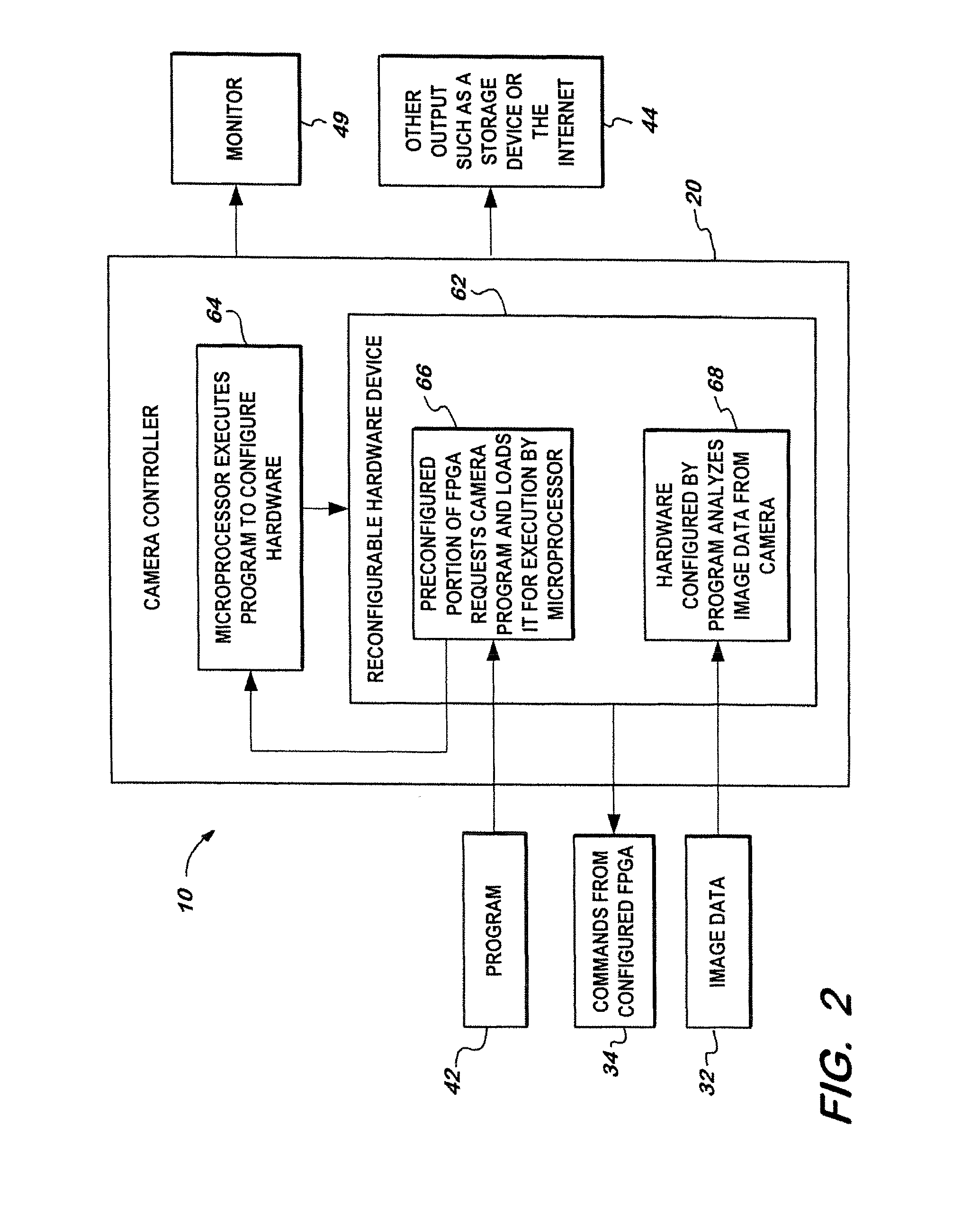
The invention is a programmable camera control unit that can be used with different types of cameras. It includes a camera control unit that can be programmed with software to process image data from the camera. The control unit has configurable hardware that can be programmed to work with different cameras. The software can be stored on a storage device and can be downloaded from the control unit. The control unit can also have a field programmable gate array (FPGGA) for configuring the control unit. The FPGAs can be programmed with the software to make the control unit compatible with different cameras. The video imaging system may also include a storage device for storing the software and a microprocessor for executing the software. The invention allows for easy customization and flexibility in camera control.

Problems solved by technology

Traditionally, control units were compatible with a limited number of CCDs because the control units' hardware, through which commands were sent and image signals were received, was difficult to configure to communicate with the many different types of cameras in the market.
Further, depending upon the manufacturer, there may be differences among CCDs and, in particular, when some, but not all, CCDs are replaced.
In addition, as changes and improvements are made to the cameras, a control unit's hardware, which was configured to be compatible with older cameras, may become incompatible and may need to be upgraded as well.
Moreover, control units are generally made to be used with cameras currently in existence and are not designed to future camera configurations not yet known.
Hence, control units are typically not made to be compatible with future camera technologies and the differences among older and newer cameras may contribute toward compatibility problems between control units and cameras and, therefore, control units are generally compatible with a selected number of cameras.
Consequently, control units have become an added expense often associated when changing CCDs or cameras.
This expense is then possibly passed onto consumers.

Method used


Image

  • Programmable camera control unit with updatable program
  • Programmable camera control unit with updatable program
  • Programmable camera control unit with updatable program

Examples


Embodiment Construction

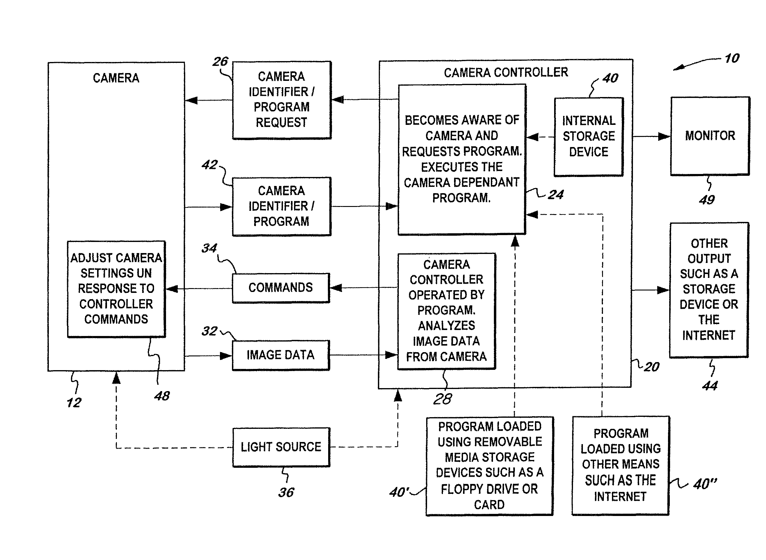
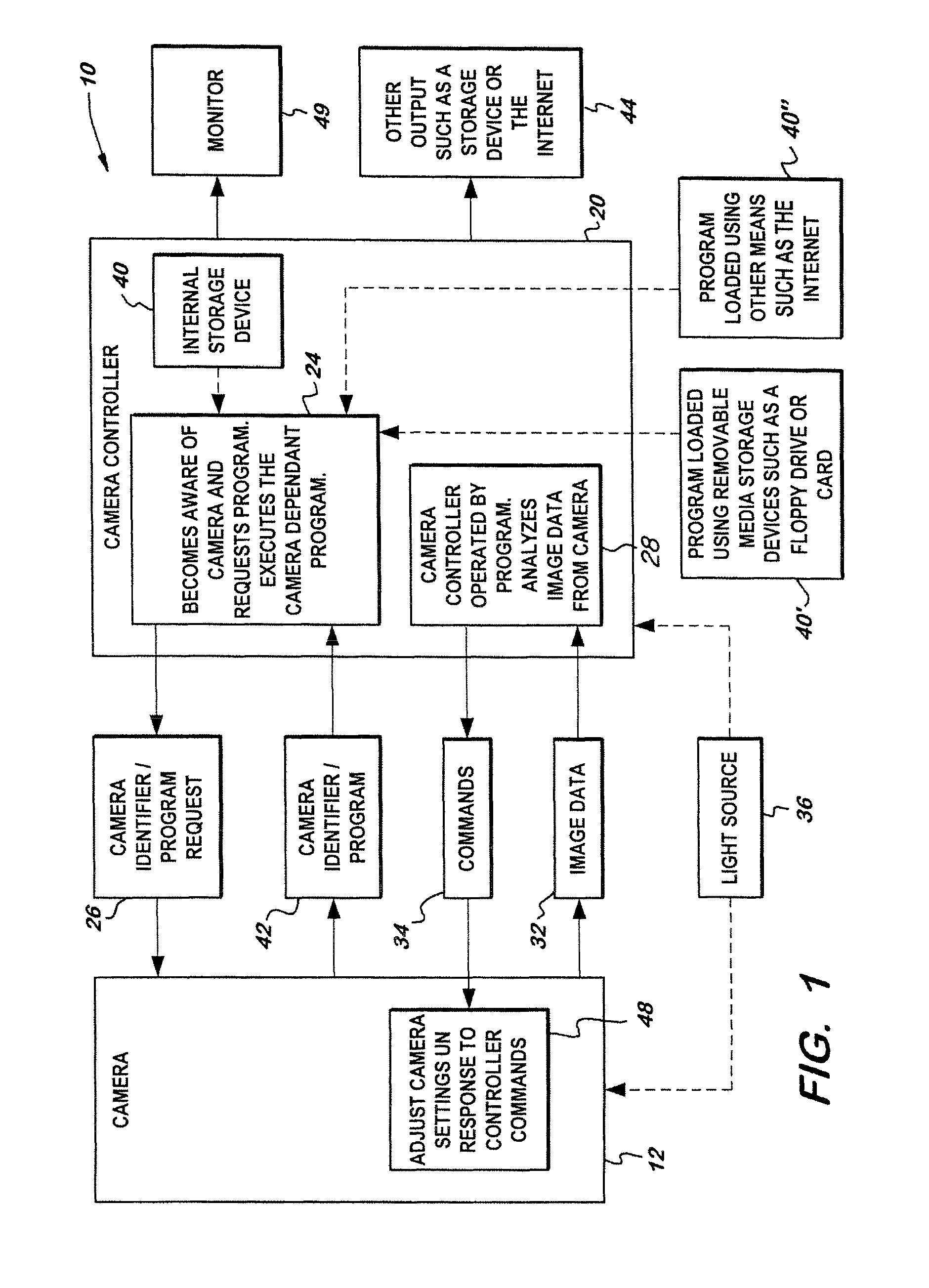
[0031]FIG. 1 depicts a system 10 for video imaging, comprising a camera 12 for transmitting image data and camera control unit 20 for receiving and processing image data, particularly endoscopic video imaging. System 10 further includes storage device 40 for storing program 42 and an electronic system for determining when camera 12 is in communication with camera control unit 20 and for retrieving program 42.

[0032]Camera 12 captures image data and transmits it to camera control unit 20 to process a displayable image. Camera 12 may include one or more charge coupled devices (“CCD”), including different types of CCDs or multiple ones of a single type of CCD or may include a C-MOS device. Camera 12 may further include known cameras in the field and / or novel cameras including storage device 40 for storing program 42.

[0033]Control unit 20 is the brain of the camera. It commands camera 12 to adjust camera settings and desired image data. Control unit 20 then receives and processes the ima...


PUM


Abstract

A video imaging system with a camera coupled to a camera control unit, the camera having a program stored thereon and the camera control unit comparing the program version stored on the camera with another version of the program such that the newer version of the program is loaded onto the camera control unit and camera control unit is programmed with the newer version of the program to enable the camera control unit to process image data received from the camera.

Description

CROSS-REFERENCE TO RELATED APPLICATIONS[0001]This application is a continuation-in-part of 10 / 039,931 filed Nov. 9, 2001, now U.S. Pat. No. 7,212,227 is-sued May 1, 2007.FIELD OF THE INVENTION[0002]The invention relates to a camera control unit capable of processing a video signal from many different types of video cameras and, more particularly, the invention relates to programming and / or configuring the camera control unit with the newest available version of a program(s).BACKGROUND OF THE INVENTION[0003]Cameras and camera control units (“control unit”) are generally used together to capture and process images. Cameras may include charge couple devices (“CCD”) and they typically capture, or pick up, images and send an image signal to the control unit. This image signal may be sent to the control unit via a cable or it may be sent through a wireless communication. Upon receiving the image signal, the control unit processes it into a displayable image, such as an image on a monitor ...

Claims


Application Information

Patent Timeline
Patent Type & Authority Patents(United States)
IPC IPC(8): H04N5/225A61B1/04H04N7/18H04N25/00
CPCA61B1/042A61B1/045G06F8/65H04N5/232H04N5/23209H04N2005/2255G06F8/665G06F8/654H04N23/555H04N23/663H04N23/60
Inventor CHATENEVER, DAVIDAMLING, MARC R.
Owner KARL STORZ IMAGING INC
Learn More