
Implantable therapeutic substance delivery device with reservoir volume sensor

a technology of reservoir volume and therapeutic substance, which is applied in the direction of instruments, prostheses, liquid/fluent solid measurement, etc., can solve the problems of clinicians not fully understanding the amount of therapeutic substance currently contained in the device, clinicians may still experience difficulties in determining whether refilling the reservoir is needed, and the reservoir is depleted

Active Publication Date: 2011-12-27
MEDTRONIC INC
View PDF16 Cites 21 Cited by
  • Summary
  • Abstract
  • Description
  • Claims
  • Application Information

AI Technical Summary

Benefits of technology

Enables precise measurement of the residual volume within the reservoir, providing clinicians with accurate information to determine if refilling is needed, ensuring consistent therapy delivery without degrading the sensor accuracy or compromising the integrity of the therapeutic substance.

Problems solved by technology

Regardless of exact design, over time, the therapeutic substance in the reservoir becomes depleted and it is necessary to refill the device with a new supply of therapeutic substance.
While efforts have been made to optimize the refill port design, for example in terms of ease of identification and needle insertion, clinicians may still experience difficulties in determining whether refilling of the reservoir is needed.
That is to say, while available devices are capable of ensuring consistent refilling via percutaneous interface, the clinician may not have a complete understanding of how much therapeutic substance is currently contained within the device.
In light of the hermetic, metallic barrier commonly associated with the reservoir along with the importance of preventing contact between the contained therapeutic substance and materials that are otherwise incompatible with the media, no viable device for measuring therapeutic substance reservoir volume has heretofore been available.

Method used


Image

  • Implantable therapeutic substance delivery device with reservoir volume sensor
  • Implantable therapeutic substance delivery device with reservoir volume sensor
  • Implantable therapeutic substance delivery device with reservoir volume sensor

Examples


Embodiment Construction

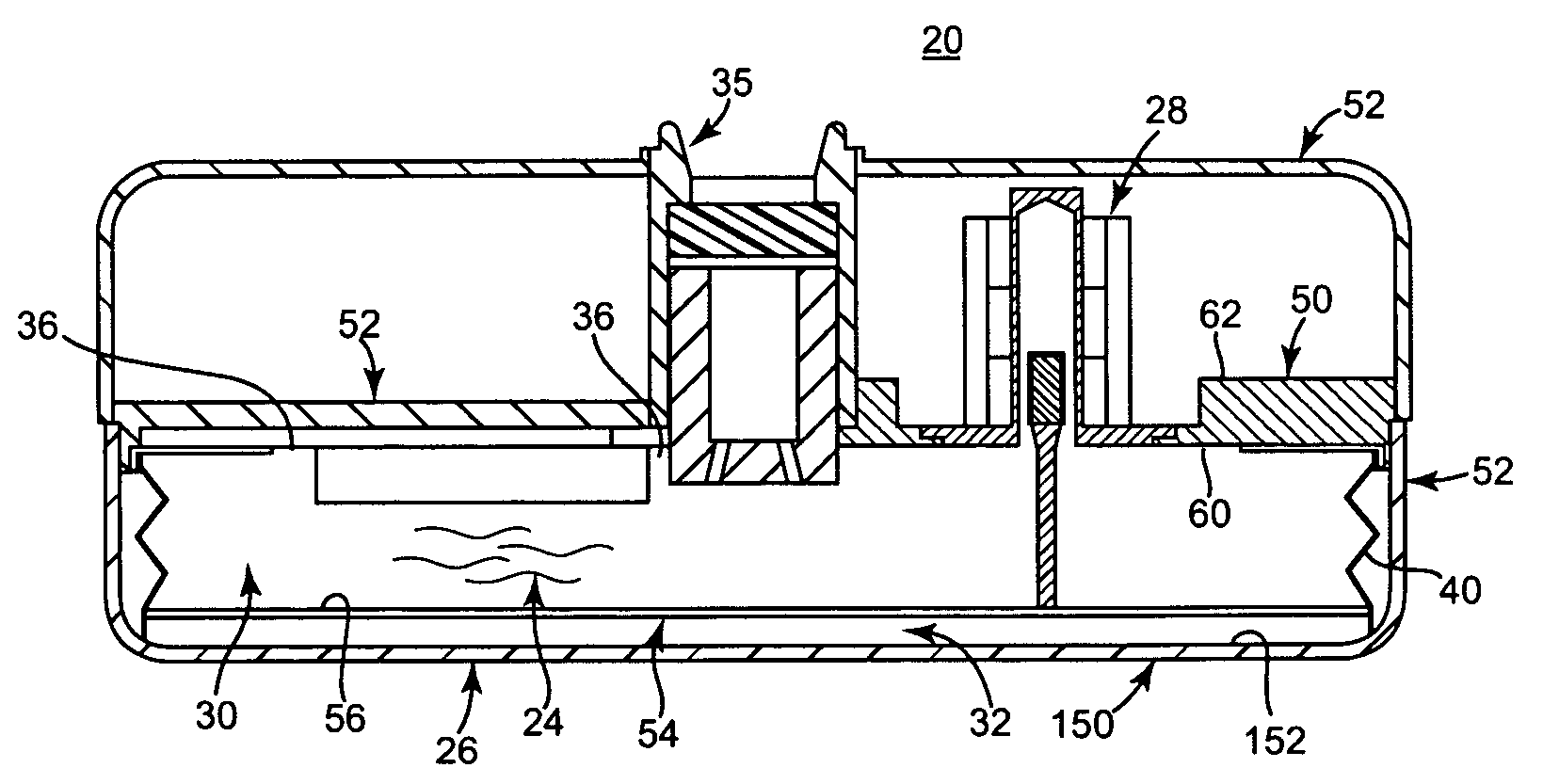
[0016]One embodiment of an implantable therapeutic substance delivery device 20 in accordance with principles of the present invention is shown in FIGS. 1A and 1B, along with an implantable intrathecal catheter 22. In general terms, the implantable therapeutic substance delivery device 20, also known as a drug pump, can assume a variety of forms, and can be provided as part of an intrathecal infusion system that further includes an external programmer (not shown), for example as provided with a SynchroMed® EL Infusion System available from Medtronic, Inc., of Minneapolis, Minn. Regardless, the implantable therapeutic substance delivery device 20 operates to infuse a therapeutic substance 24 (drawn generally in FIG. 1A) into a patient via the catheter 22. The therapeutic substance 24 can be any infusion agent, product, or substance intended to have a therapeutic effect such as pharmaceutical compositions, genetic materials, biologics, and others (e.g., insulin, saline solution, fluor...


PUM


Abstract

An implantable medical device for delivering a therapeutic substance including a housing and a volume sensor assembly. The housing includes a stationary wall and maintains a reservoir containing the therapeutic substance and including a base wall movable relative to the stationary wall such that reservoir volume is a function of a spacing between the base wall and the stationary wall. The volume sensor assembly includes a cap, a shaft, a target, and circuitry. The cap defines a passage extending from an open end, and is mounted to the stationary wall such that the open end is open relative to a stationary wall inner face. The shaft has a first end attached to the base wall and a second end maintaining the target otherwise movably arranged within the passage. The circuitry generates information indicative of a longitudinal position of the target relative to the cap, and thus of the reservoir volume.

Description

BACKGROUND OF THE INVENTION[0001]The present invention relates to implantable medical devices for delivering a liquid therapeutic substance to a delivery site within a patient. More particularly, it relates to systems and methods for estimating or indicating a residual volume of therapeutic media contained within a reservoir of an implantable delivery device, and related methods of operating the implantable delivery device.[0002]A variety of implantable medical devices are available for treating patients. For example, implantable therapeutic substance delivery devices are typically used to deliver infusion media or therapeutic substance (such as medication) to a patient at a regulated dosage. The implantable therapeutic substance delivery device (sometimes referred to as a drug pump or medicament pump) is implanted by a clinician into a patient at a location appropriate for the therapy. Typically, an infusion catheter is connected to an outlet of the device, and is implanted / positio...

Claims


Application Information

Patent Timeline
Patent Type & Authority Patents(United States)
IPC IPC(8): A61K9/22G01F17/00A61M31/00A61M37/00A61M1/00
CPCA61F2/022A61M5/14276A61M2205/3317A61M2205/3379A61M2205/3389A61M2209/045
Inventor MIESEL, KEITH A.
Owner MEDTRONIC INC
Learn More