RJ-45 connector

Inactive Publication Date: 2011-11-15
HON HAI PRECISION IND CO LTD
View PDF3 Cites 5 Cited by
  • Summary
  • Abstract
  • Description
  • Claims
  • Application Information

AI Technical Summary

Problems solved by technology

However, in most cases, the interface is defined in a rear end of the chassis, thus light generated by the light emitting diodes is only seen from the back of the chassis, which is inconvenient.

Method used


Image

  • RJ-45 connector
  • RJ-45 connector
  • RJ-45 connector

Examples


Embodiment Construction

[0010]The disclosure, including the accompanying drawings in which like references indicate similar elements, is illustrated by way of examples and not by way of limitation. It should be noted that references to “an” or “one” embodiment in this disclosure are not necessarily to the same embodiment, and such references mean at least one.

[0011]Referring to FIG. 1, one embodiment of a Registered Jack-45 (RJ-45) connector 30 includes a main body 34, a light guide member 32 fitting about a rear end of the main body 34, and a cable 36 extending from the rear end of the main body 34.

[0012]An elastic latch 342 is formed on a front end of a sidewall of the main body 34 opposite to the rear end. A raised portion 346 is formed on a bottom of the rear end of the main body 34.

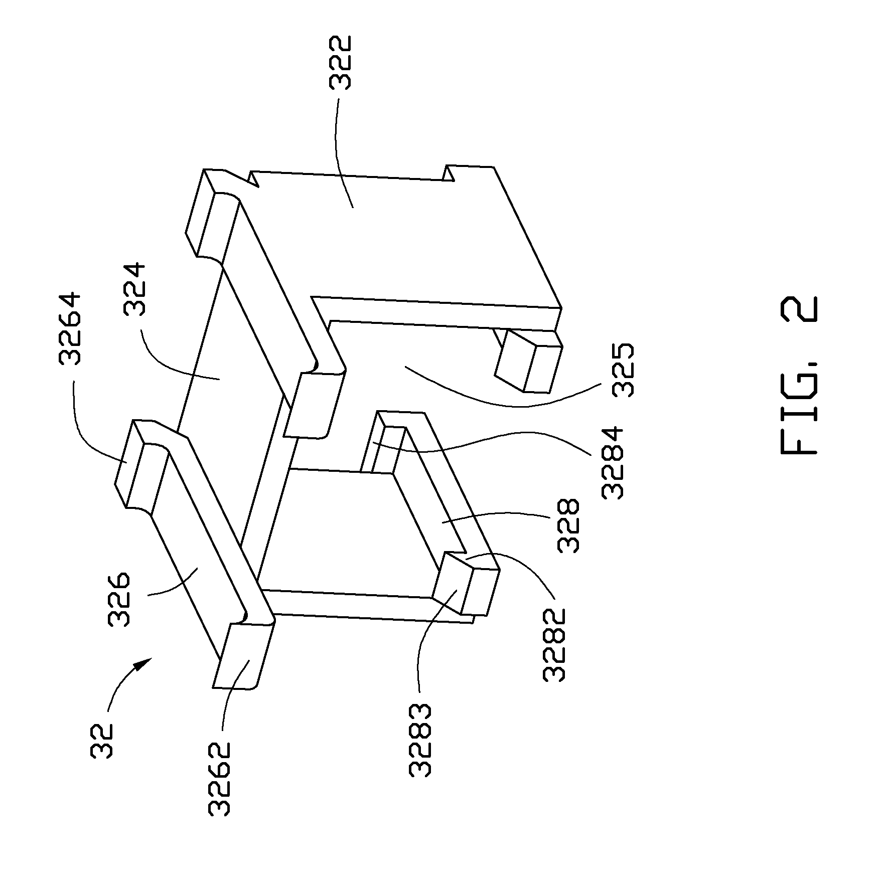
[0013]Referring to FIG. 2, the light guide member 32 can be substantially U-shaped and include opposite sidewalls 322, and a supporting portion 324. Opposite ends of the supporting portion 324 are connected to tops of the s...


PUM


Abstract

A Registered Jack-45 connector matching a connector with two light emitting diodes, includes a main body engaged with the connector, and a light guide member fitting about the main body. The light guide member includes two light guide posts. Each light guide post includes a front end aligning with and facing a corresponding light emitting diode, and a rear end opposite to the first end. The light guide posts transmit light emitted by the light emitting diodes from the front ends to the rear ends of the light guide posts.

Description

[0001]This relevant subject matter is disclosed in a co-pending U.S. patent application Ser. No. 12 / 825,309 entitled “RJ-45 connector,” which is assigned to the same assignee as this patent application.BACKGROUND[0002]1. Technical Field[0003]The present disclosure relates to a Registered Jack-45 (RJ-45) connector.[0004]2. Description of Related Art[0005]RJ-45 connectors are widely used in network communication. In use, an RJ-45 connector is engaged in an interface of a chassis of a computer or a server. The interface includes two light emitting diodes, used to indicate whether the network connection is working properly. However, in most cases, the interface is defined in a rear end of the chassis, thus light generated by the light emitting diodes is only seen from the back of the chassis, which is inconvenient.BRIEF DESCRIPTION OF THE DRAWINGS[0006]Many aspects of the present embodiments can be better understood with reference to the following drawings. The components in the drawing...

Claims


Application Information

Patent Timeline
Patent Type & Authority Patents(United States)
IPC IPC(8): H01R3/00
CPCH01R13/7175H01R24/64
Inventor SUN, ZHENG-HENG
Owner HON HAI PRECISION IND CO LTD
Why Eureka
Try Eureka