Wire winding spool

a technology of winding spools and wires, applied in the field of wire winding spools, can solve the problems of a certain constructive complexity of known spools, and achieve the effect of maximum simplicity

Inactive Publication Date: 2011-11-01
VELAWORKS S R O
View PDF19 Cites 1 Cited by
  • Summary
  • Abstract
  • Description
  • Claims
  • Application Information

AI Technical Summary

Benefits of technology

[0004]Therefore the aim of the present invention is to provide a spool which has maximum simplicity.

Problems solved by technology

Known spools have a certain constructive complexity, which derives in particular from assemblies obtained by welding.

Method used


Image

  • Wire winding spool
  • Wire winding spool
  • Wire winding spool

Examples


Embodiment Construction

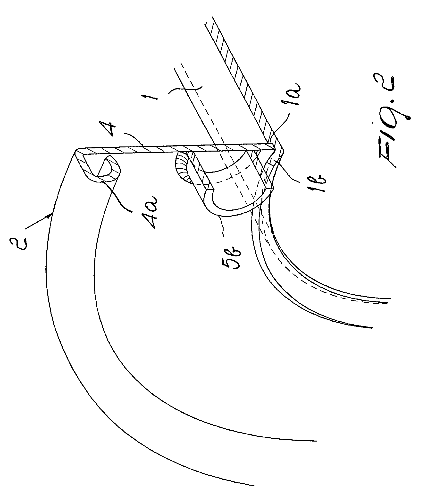
[0012]With reference to FIGS. 1 and 2, the reference numeral 1 designates a tubular body for supporting a coil of wire, which is provided at the ends with two wall elements 2 and 3, which are mirror-symmetrically identical.

[0013]Therefore, only the element 2 is described; it is formed by a flat flange 4 with a stiffening fold 4a at the outer edge and welded driving pins 5a, 5b; as regards such pins, it should be considered that they might be absent in the element 3.

[0014]The flange 4 is associated with the end of the tubular body 1 so as to rest against an abutment 1a provided on the outer surface of the wall of the body, clamped against it by a fold 1b of the end portion of the wall, which is obtained very easily by plastic deformation of the material.

[0015]It should be noted that the fold 1b, besides performing the function indicated above, acts as an effective guide for the penetration of the spindle designed to support the spool during operation.

[0016]A first variation of the in...


PUM


Abstract

A wire winding spool, comprising a tubular body for supporting a coil of wire provided, at its ends, with wall elements for containing the coil, at least one of the wall elements being provided with at least one pin for engaging means for turning the spool, each wall element being associated with the corresponding end of the tubular body so as to rest against an abutment provided on the outer surface of the wall of the body, clamped against it by a fold of the end portion of the wall.

Description

TECHNICAL FIELD[0001]The present invention relates to a wire winding spool.BACKGROUND ART[0002]It is known that spools for winding wire which comprise a tubular body for supporting the coil of wire, provided at its ends with wall elements for containing the coil, are widely used in the industrial field.[0003]Known spools have a certain constructive complexity, which derives in particular from assemblies obtained by welding.DISCLOSURE OF THE INVENTION[0004]Therefore the aim of the present invention is to provide a spool which has maximum simplicity.[0005]This aim is achieved by a wire winding spool, according to the invention, comprising a tubular body for supporting a coil of wire provided, at its ends, with wall elements for containing said coil, at least one of the wall elements being provided, at the surface directed outwardly, with at least one pin for engaging means for turning said spool, characterized in that each wall element is associated with the corresponding end of the t...

Claims


Application Information

Patent Timeline
Patent Type & Authority Patents(United States)
IPC IPC(8): B65H75/14
CPCB65H75/14B65H2701/5134
Inventor RUGGENENTI, LUCA
Owner VELAWORKS S R O
Why Eureka
Try Eureka