Estimation of exhaust gas temperature at the output of the EGR circuit of a combustion engine
a technology of exhaust gas temperature and combustion engine, which is applied in the direction of machines/engines, electric control, instruments, etc., can solve the problems of insufficient accuracy and reliability of models, inability to accurately estimate the temperature of exhaust gas, and high cost, so as to improve the accuracy of estimated temperature
- Summary
- Abstract
- Description
- Claims
- Application Information
AI Technical Summary
Benefits of technology
Problems solved by technology
Method used
Image

Examples
first embodiment
[0042]The invention described below involves the following two embodiments, enabling the exhaust gas temperature at the outlet of the EGR cooler to be estimated:[0043]development of equations closely modeling physical phenomena, the equations being reduced to their strictest necessary for them to be able to be integrated into an engine software package; an appreciable improvement in the precision of the estimator of the exhaust gas temperature in the EGR circuit is obtained, given that the model used is closer to reality; and[0044]drastic simplification of the equations considered in the the objective is to minimize the computing time and the software size.
[0045]The two proposed embodiments are readily applicable to all internal combustion engines equipped with EGR circuits (diesel engine, gasoline engine, etc.).
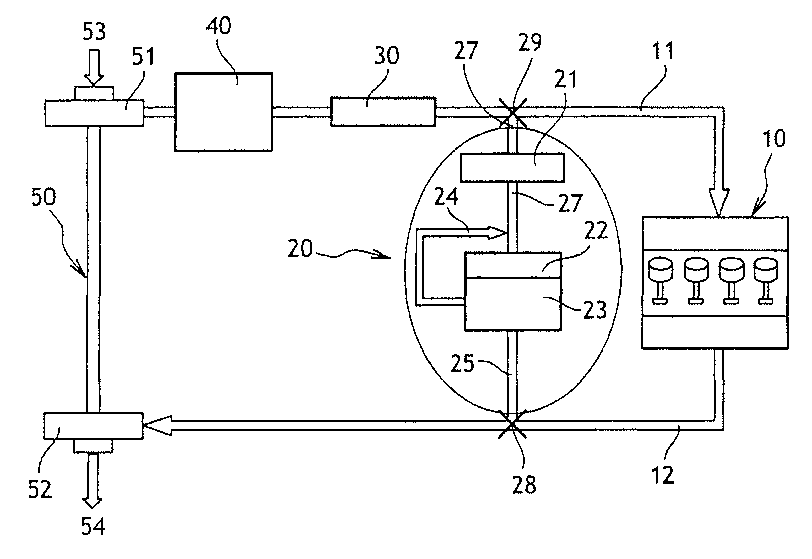
[0046]FIG. 1 shows an example of an internal combustion engine compartment.
[0047]This engine compartment comprises an internal combustion engine 10 supplied with air via an ...
1st embodiment
1st Embodiment
Development of Physics Equations
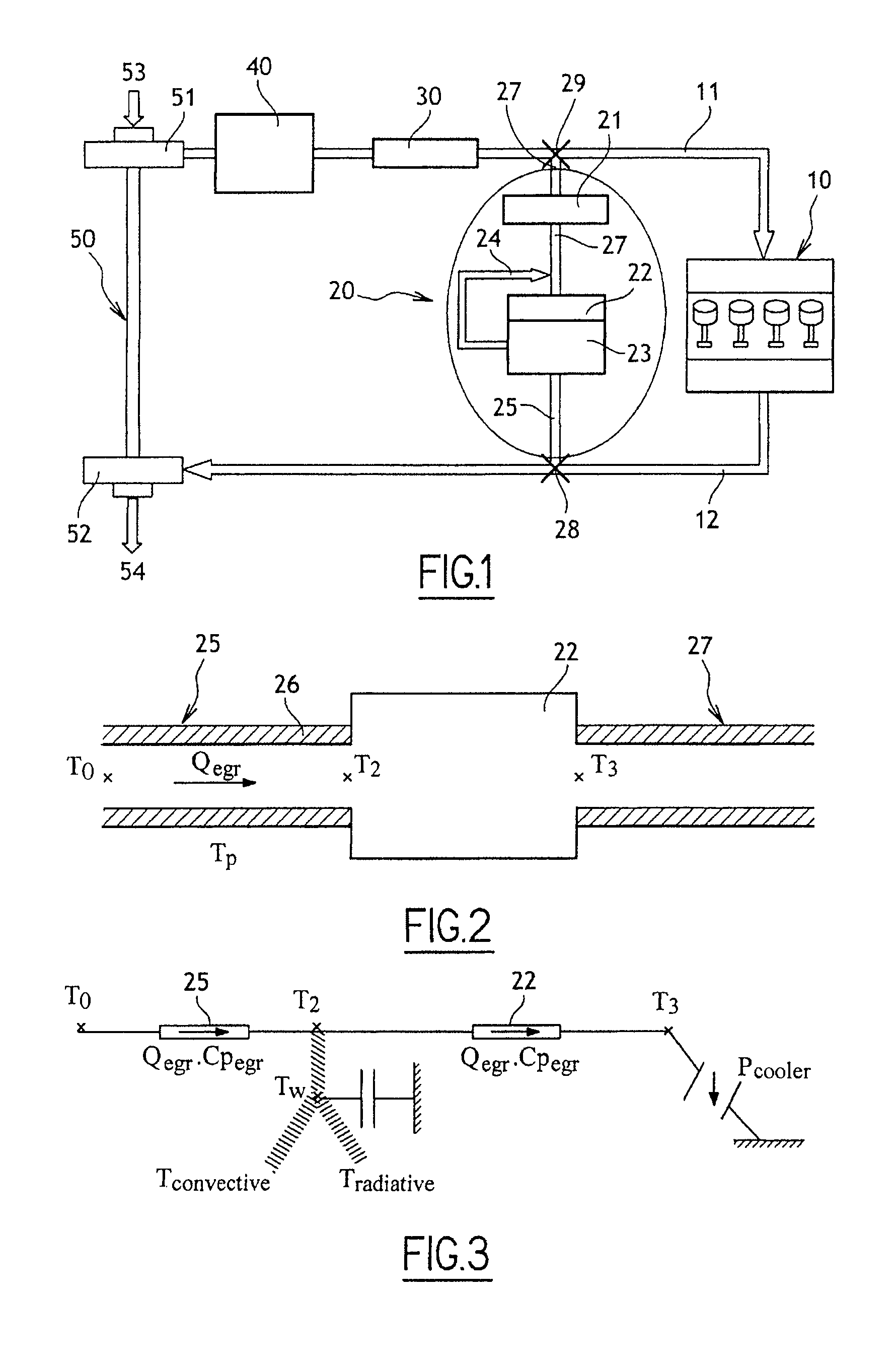
[0059]To estimate the heat exchange within an EGR circuit 20 correctly, it is necessary to take into account:[0060]the internal heat exchange between the gas and the wall 26 of the inlet duct 25;[0061]the external heat exchange between the wall 26 of the inlet duct 25 and the environment of the engine compartment, two types of heat exchange being predominant in the engine compartment:[0062]convective heat exchange due to the flow of air around the PU (power unit) and[0063]radiative heat exchange between the various components under the hood (cylinder head, exhaust manifold, turbocharger, bulkhead, “ski”, etc.);[0064]cooling of the gas through the EGR cooler.
[0065]FIG. 3 shows a “thermal electrical” analogy used to establish the energy balance of the EGR circuit 20. This method provides an equivalence between the thermal system of FIG. 2 and the electrical system of FIG. 3.
[0066]It should be noted that the entire wall of the EGR tube is ...
2nd embodiment
2nd Embodiment
Drastic Simplification of the Equations
[0102]The physics equations developed above can be integrated in a computer but they may remain relatively complicated (equations 1, 2 and 3). This is because they form a system of nonlinear differential equations (owing to the presence of terms in T4) that are strongly coupled.
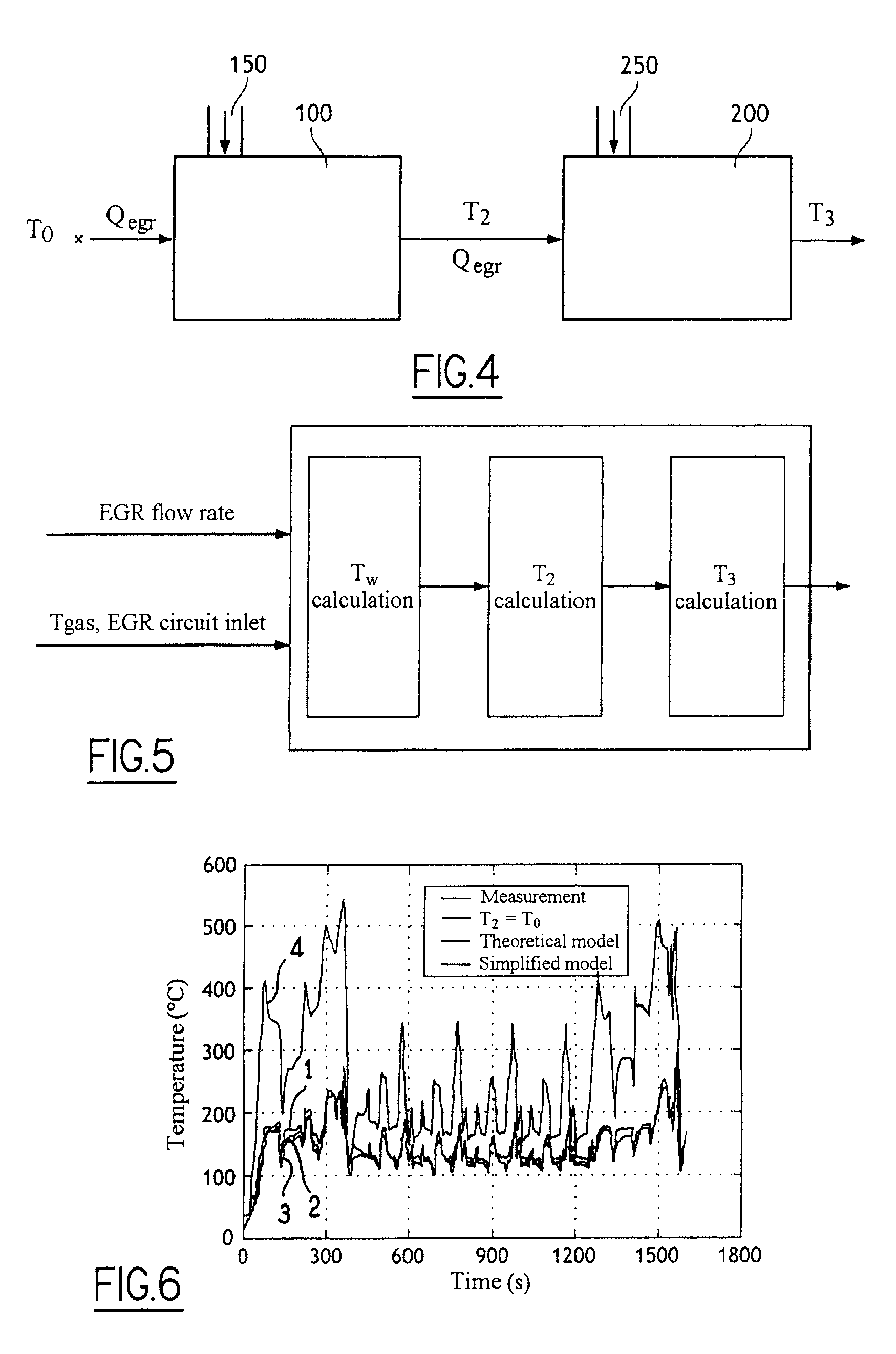
[0103]It would therefore be desirable to simplify this system so as to obtain a system of independent linear first-order differential equations. For this purpose, with reference to FIG. 4, the EGR circuit 20 is considered to be a combination of two heat exchangers 100 and 200 in series.
[0104]The first heat exchanger 100 consists of the inlet duct 25 upstream of the cooler 22. The EGR gas cooled by the ambient medium 150 within the engine compartment (Tradiative and Tconvective as explained above) flows through this heat exchanger 100. The gas temperature at the outlet of this first heat exchanger 100 is the temperature T2.
[0105]The second heat exchanger 200...
PUM
 Abstract
Description
Claims
Application Information
 - R&D
- Intellectual Property
- Life Sciences
- Materials
- Tech Scout
- Unparalleled Data Quality
- Higher Quality Content
- 60% Fewer Hallucinations
Browse by: Latest US Patents, China's latest patents, Technical Efficacy Thesaurus, Application Domain, Technology Topic, Popular Technical Reports.
© 2025 PatSnap. All rights reserved.Legal|Privacy policy|Modern Slavery Act Transparency Statement|Sitemap|About US| Contact US: help@patsnap.com