
Vacuum wound dressing

a wound dressing and vacuum technology, applied in the field of vacuum wound dressing, can solve the problems of not being recognized that such methods can be effectively combined

Active Publication Date: 2011-10-11
CONVATEC TECH INC
View PDF9 Cites 122 Cited by
  • Summary
  • Abstract
  • Description
  • Claims
  • Application Information

AI Technical Summary

Problems solved by technology

It is believed that it has not been recognized that such methods can be effectively combined with gel-forming wound care products placed against the wound to which vacuum is applied.

Method used


Image

  • Vacuum wound dressing
  • Vacuum wound dressing
  • Vacuum wound dressing

Examples


Embodiment Construction

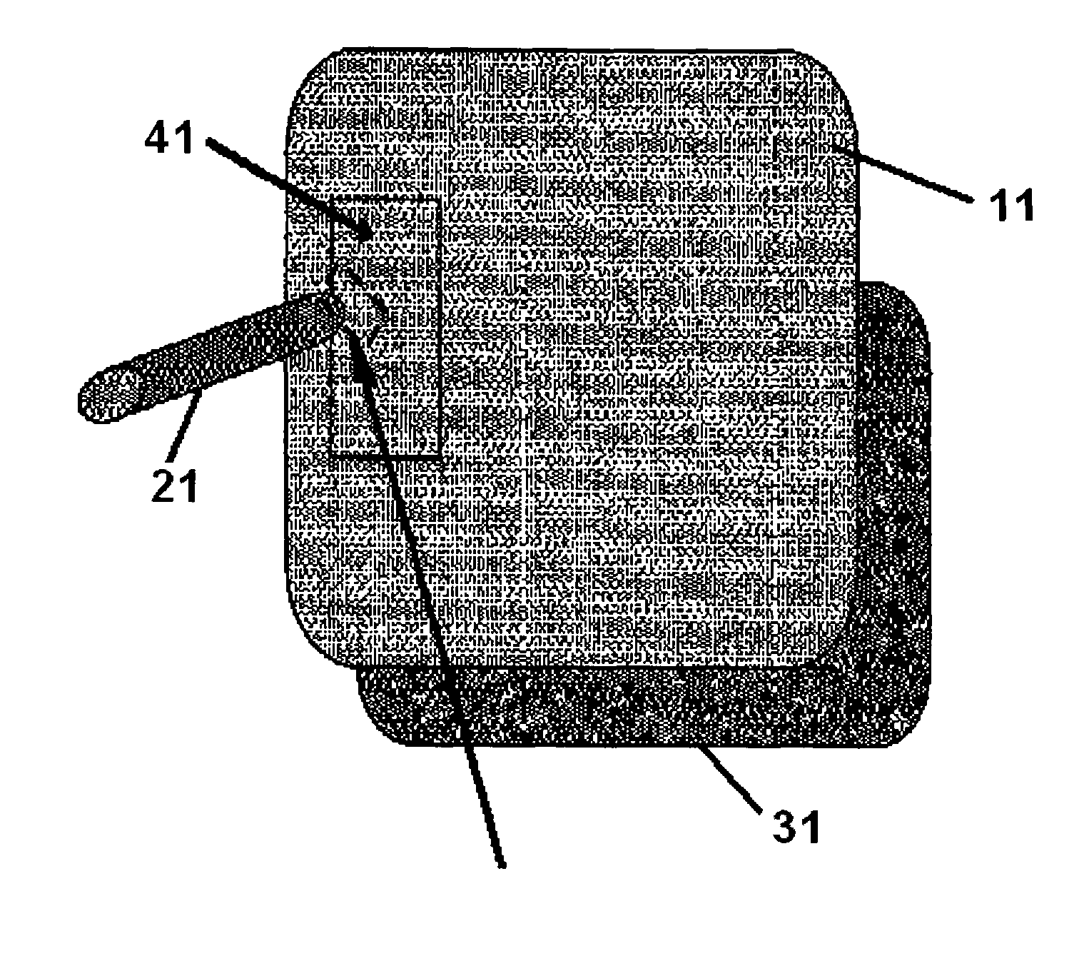
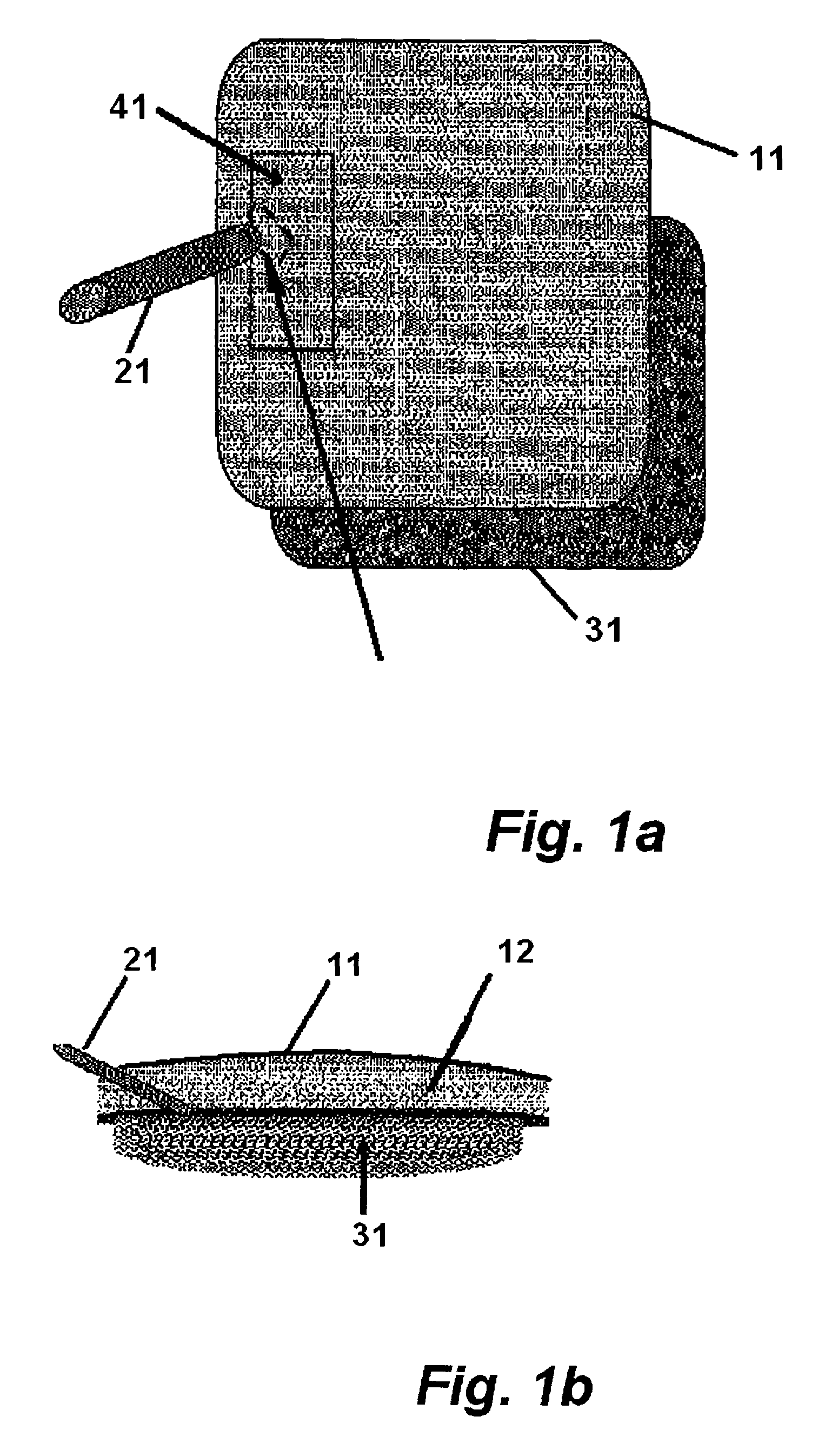
[0011]The outer dressing used in the vacuum method can include a vacuum sealing outer layer that is film layer 11, and a foam layer 12. As illustrated in FIGS. 1a and 1b, a vacuum source connector 21 (e.g., silicone tubing) can be slotted through film layer 11 and foam layer 12, and sealed with another adhesive film 41. Film 41 can be, for example, the Opsite™ film dressing from Smith & Nephew (Cambridge, United Kingdom). The vacuum permeable foam layer 12 is separated from direct contact with the wound by wound contact layer 31.

[0012]As illustrated, the source of vacuum (illustrated as tubing) is favorably separated from the wound by a wound contact layer, or a portion of a wound contact layer.

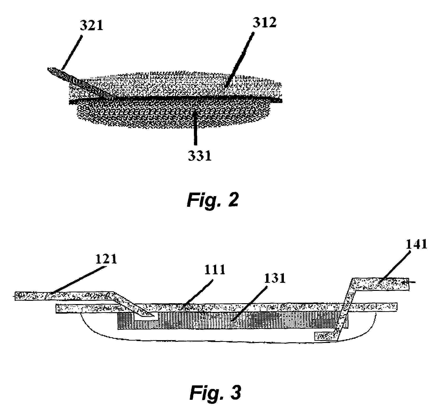
[0013]As illustrated in FIG. 2, the outer layer of the vacuum sealing layer can be foam layer 312, with the porosity of the foam layer selected retain a portion of the vacuum at the wound site. Foam layer 312 is separated from direct contact with the wound by wound contact layer 331. Vacuum s...


PUM


Abstract

Provided, in one embodiment, is a vacuum wound dressing for covering a wound bed comprising: a wound contact layer comprising a fibrous blend or fibrous material that forms a cohesive gel when wetted by wound exudate; a source of vacuum situated to be separated from the wound bed by the wound contact layer; and a vacuum sealing layer covering the wound contact layer and adapted to retain relative vacuum in the wound contact layer, wherein (i) the dressing is essentially missing a non-gelling, foam layer in which the source of vacuum is situated or (ii) the vacuum sealing layer comprises as an outer layer a foam layer.

Description

[0001]This application claims the priority of U.S. Provisional Application No. 60 / 625,488, filed Nov. 5, 2004.[0002]The present invention relates to methods, devices and kits for treating a wound with a dressing and vacuum.[0003]Vacuum has been used to increase blood flow to wound tissue and to remove exudate from the wound site. It is believed that it has not been recognized that such methods can be effectively combined with gel-forming wound care products placed against the wound to which vacuum is applied.SUMMARY OF THE INVENTION[0004]Provided, in one embodiment, is a vacuum wound dressing for covering a wound bed comprising: a wound contact layer comprising a fibrous blend or fibrous material that forms a cohesive gel when wetted by wound exudate; a source of vacuum situated to be separated from the wound bed by the wound contact layer; and a vacuum sealing layer covering the wound contact layer and adapted to retain relative vacuum in the wound contact layer, wherein (i) the dr...

Claims


Application Information

Patent Timeline
Patent Type & Authority Patents(United States)
IPC IPC(8): A61M1/00A61M27/00A61M35/00A61F13/00
CPCA61M1/0096A61M1/0088A61M1/0076A61M1/0084A61M1/804A61M1/882A61M1/84A61M1/85A61M1/915A61M1/92A61F2013/00089A61F13/00068A61F2013/00217
Inventor ADAMS, SIMONBISHOP, STEPHENGRIFFITHS, BRYANSHAW, HELEN
Owner CONVATEC TECH INC
Learn More