Lever type connector

a lever-type connector and connector technology, applied in the direction of coupling device connection, engagement/disengagement of coupling parts, electrical apparatus, etc., can solve the problems of connector vibration, inability to maintain the engagement of the plug-side connector b>901/b>, etc., to prevent erroneous operation of the lock portion, good operability, high reliability

Inactive Publication Date: 2011-10-11
MOLEX INC
View PDF3 Cites 13 Cited by
  • Summary
  • Abstract
  • Description
  • Claims
  • Application Information

AI Technical Summary

Benefits of technology

[0010]Therefore, it is an object of the Present Invention to obviate the above-described problems encountered by the conventional connector, and to provide a connector which has good operability and high reliability. To this end, a lever, configured to be rotatable so as to engage an engagement member of a counterpart connector, is provided with a lock portion that is slidable relative to a body portion of the lever. The lever is further provided with a latching portion capable of being latched with the body portion at a lock position and a lock release position, so that the lever becomes unable to rotate by being locked at a fitting completion position. The lock portion is not slid from the lock position and thus is not unnecessarily unlocked. As a result, the engagement with the counterpart connector is not released upon reception of any unexpected external force. Further, an operator can perceive a sense of click-feeling when the lock portion is slid from either the lock position or the lock release position, and thus an erroneous operation of the lock portion can be prevented.
[0016]In accordance with the Present Invention, the cable includes a lever that is configured to be rotatable to thereby be engaged with an engagement member of a counterpart connector, a lock portion that is slidable relative to a body portion of the lever, and a latching portion capable of latching the lock portion at a lock position and a lock release position with respect to the body portion. Owing to this arrangement, the lever becomes unable to rotate by being locked at a fitting completion position, and the lock portion is not slid from the lock position and thus is not unnecessarily unlocked. Therefore, the engagement with the counterpart connector is not released upon being subjected to an unexpected external force such as an impact force or vibration. Furthermore, an operator can perceive a sense of click-feeling when the lock portion is slid from the lock position and the lock release position, and thus any erroneous operation on the lock portion can be prevented. Accordingly, it is possible to provide good operability and high reliability.

Problems solved by technology

As a result, the engagement with plug-side connector 901 might not be maintained.
In particular, when the connector is mounted on a vehicle, the connector may be subject to vibration consistent with the running of the vehicle.

Method used


Image

  • Lever type connector
  • Lever type connector
  • Lever type connector

Examples


Embodiment Construction

[0046]While the Present Invention may be susceptible to embodiment in different forms, there is shown in the Figures, and will be described herein in detail, specific embodiments, with the understanding that the disclosure is to be considered an exemplification of the principles of the Present Invention, and is not intended to limit the Present Invention to that as illustrated.

[0047]In the embodiments illustrated in the Figures, representations of directions such as up, down, left, right, front, rear and the like, used for explaining the structure and movement of the various elements of the Present Invention, are not absolute, but relative. These representations are appropriate when the elements are in the position shown in the Figures. If the description of the position of the elements changes, however, it is assumed that these representations are to be changed accordingly.

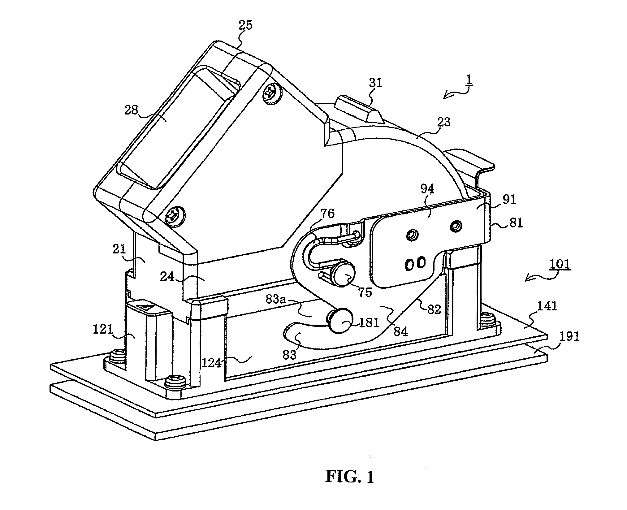
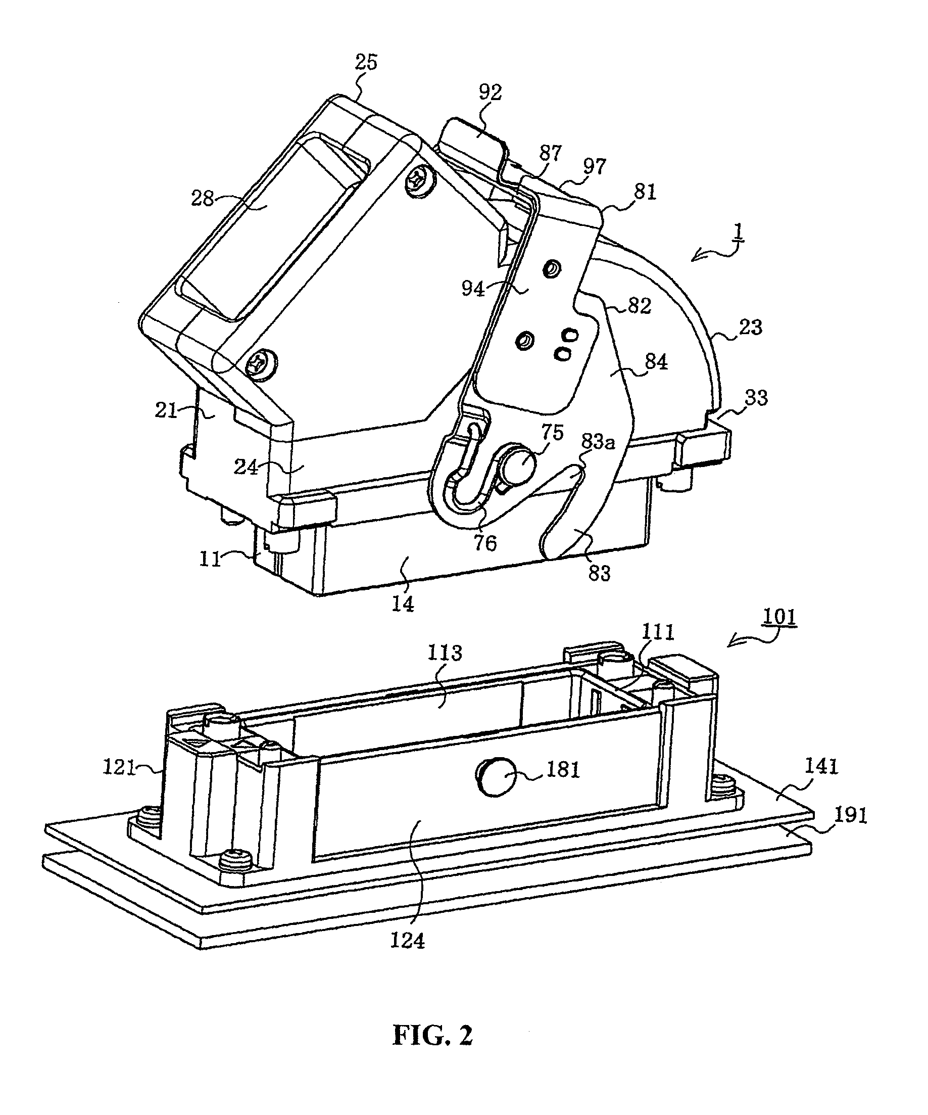
[0048]Referring to FIGS. 1-5, cable-side connector 1 (hereinafter referred to as a cable connector) is engaged...


PUM


Abstract

A connector comprises housing, a lever and a lock portion. The lever, attached to the housing, is configured to be rotatable between a first position, where the connector is initially fit to another is established, and a second position, where the fitting is completed. The lock portion is capable of locking the lever at the second position, is slidably attached to a body portion of the lever, and is configured to be slid between a lock position (where the lever is locked) and a lock release position (re-leased). The lever is provided with a positioning latch-portion, which is configured to latch the lock portion at the lock position and the lock release position and is pro-vided with a concaved latch-portion and a convexed latch-portion that is configured to be elastically displaced to be engaged in or disengaged from the concaved latch-portion.

Description

BACKGROUND OF THE INVENTION[0001]1. Field of the Invention[0002]The Present Invention relates generally to a connector, and, more particularly, to a connector having a lockable engagement mechanism so as to maintain connection, even when subjected to an unexpected external force.[0003]2. Description of the Related Art[0004]Conventional connectors may be engaged, usually through “tight fitting,” with a counterpart connector arranged on a side wall of a casing used for accommodating an electronic device, such as a control unit. Such connectors are typically provided with an engagement lever, which has an engagement groove, disposed to be pivoted in a state where the engagement groove is mated with an engagement projection arranged on a housing of the counterpart connector. In this manner, the fitting force is increased to result in a secure engagement between the connectors. An example of a typical conventional connector can be found in Japanese Patent Application Laid-Open (Kokai) No...

Claims


Application Information

Patent Timeline
Patent Type & Authority Patents(United States)
IPC IPC(8): H01R13/62
CPCH01R13/62955H01R13/641H01R13/62961
Inventor KOBAYASHI, KOHTAROMATSUURA, NAOYA
Owner MOLEX INC
Why Eureka
Try Eureka