
Archery bow with force vectoring anchor

a technology of force vectoring and archery bows, which is applied in the field of compound archery bows and rotatable members, can solve the problems of bows that cannot be retracted,

Active Publication Date: 2011-09-20
MCP IP
View PDF38 Cites 51 Cited by
  • Summary
  • Abstract
  • Description
  • Claims
  • Application Information

AI Technical Summary

Benefits of technology

The invention is a compound archery bow that has a rotatable member with a power cable anchor that can be attached to the rotatable member. The power cable can be anchored to either the rotatable member or another rotatable member, allowing for more flexibility in the bow's design. The technical effect of this invention is to provide a more versatile and customizable compound archery bow that can be tailored to the user's needs and preferences.

Problems solved by technology

Each configuration can be better than other configurations in some ways, and less desirable in others.
Two cam bows have a tendency to fall out of sync, wherein the bow can experience a loss in arrow launch speed and will require maintenance to adjust cam timing.
Two cam bows often generate more vibration, noise and reverberations as an arrow is launched.
Although such configurations can be more desirable than older designs, the direct mechanical linkage does have drawbacks, such as increased friction between the moving parts, causing losses in the total energy transferred to an arrow at launch.

Method used


Image

  • Archery bow with force vectoring anchor
  • Archery bow with force vectoring anchor
  • Archery bow with force vectoring anchor

Examples


Embodiment Construction

[0036]While this invention may be embodied in many different forms, there are described in detail herein specific embodiments of the invention. This description is an exemplification of the principles of the invention and is not intended to limit the invention to the particular embodiments illustrated.

[0037]For the purposes of this disclosure, like reference numerals in the Figures shall refer to like features unless otherwise indicated.

[0038]“Archery bow” as used herein is intended to encompass any suitable type of compound archery bow, including single cam bows, CPS bows and / or cam-and-a-half bows, dual cam and / or twin cam bows, crossbows, etc.

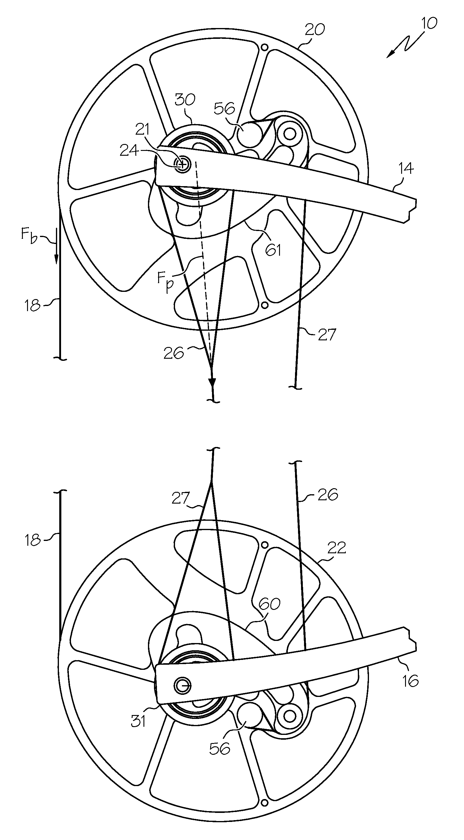
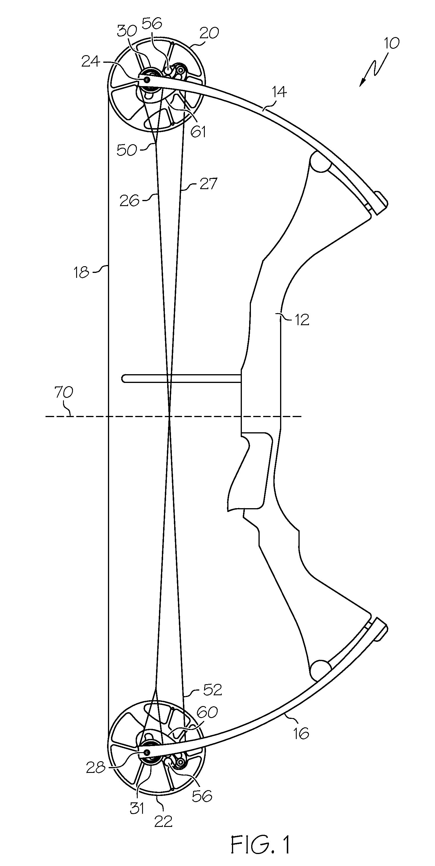
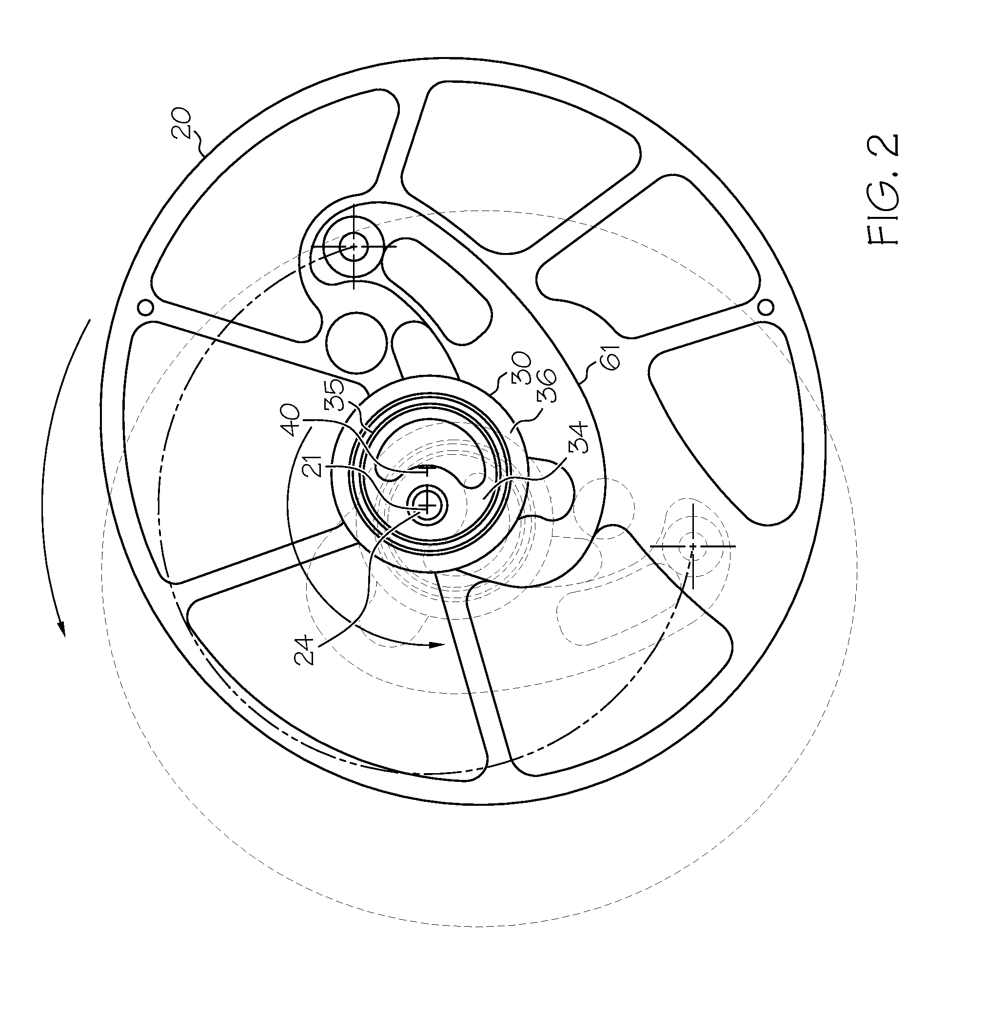
[0039]FIG. 1 shows an embodiment of an archery bow 10 comprising a force vectoring anchor 30. The vectoring anchor 30 generally allows a force vector applied by a cable 26 to transition with respect to a support point (e.g. an axle 24) as the bow is drawn.

[0040]An archery bow 10 can generally comprise a handle 12, a first limb 14 and a secon...


PUM


Abstract

In some embodiments, an archery bow comprises a rotatable member configured for rotation about a first rotatable member axis. A cable anchor is attached to the rotatable member and rotatable with respect to the rotatable member about an anchor axis. The anchor axis is offset from the rotatable member axis. The bow can further comprise a power cable anchored to said cable anchor.

Description

BACKGROUND OF THE INVENTION[0001]This invention relates generally to archery bows and more specifically to compound archery bows and rotatable members used in compound archery bows.[0002]Compound archery bows are known in the art. Various configurations have included single cam designs, modified single cam designs and two cam designs. Each configuration can be better than other configurations in some ways, and less desirable in others. For example, it is possible for some two cam bows to launch an arrow faster than a single cam design; however, rotation of the two cams must be synchronized for optimum performance. Two cam bows have a tendency to fall out of sync, wherein the bow can experience a loss in arrow launch speed and will require maintenance to adjust cam timing. Two cam bows often generate more vibration, noise and reverberations as an arrow is launched. While a single cam bow may not shoot as fast as some two cam bows, a single cam bow will often be more pleasurable to us...

Claims


Application Information

Patent Timeline
Patent Type & Authority Patents(United States)
IPC IPC(8): F41B5/00F41B5/10
CPCF41B5/105F41B5/10
Inventor MCPHERSON, MATHEW A.SIMONDS, GARY L.
Owner MCP IP
Learn More