
Control apparatus for a load supply device

a control apparatus and load supply technology, applied in the direction of dc amplifiers, dc amplifiers with modulator-demodulator, transmission systems, etc., can solve the problems of two solutions for making blocks b>61/b>, significant supply voltage variations, and cost in digital resources, so as to minimize the use of semiconductor chip area and less circuit complexity

Active Publication Date: 2011-09-13
STMICROELECTRONICS SRL
View PDF15 Cites 3 Cited by
  • Summary
  • Abstract
  • Description
  • Claims
  • Application Information

AI Technical Summary

Benefits of technology

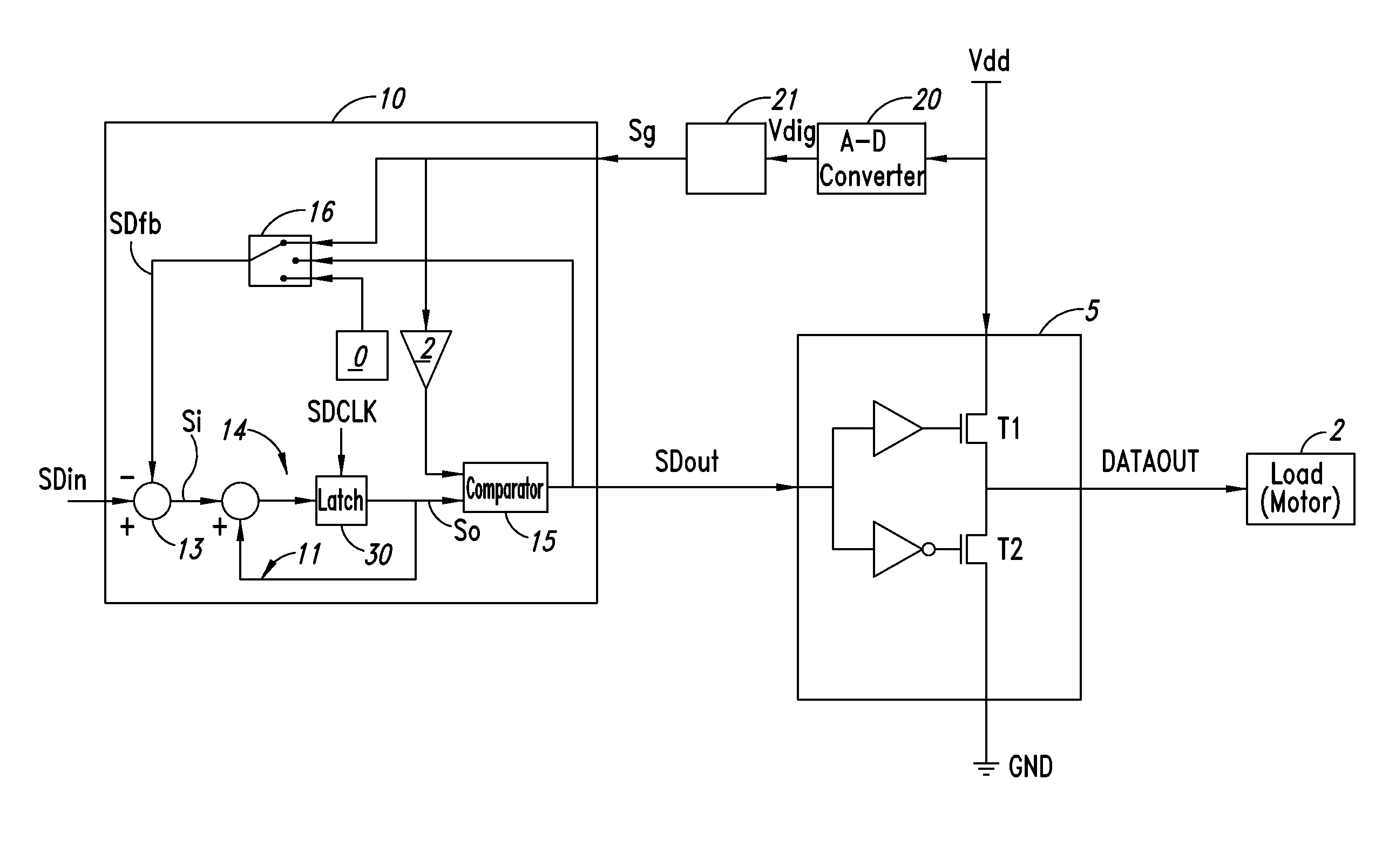
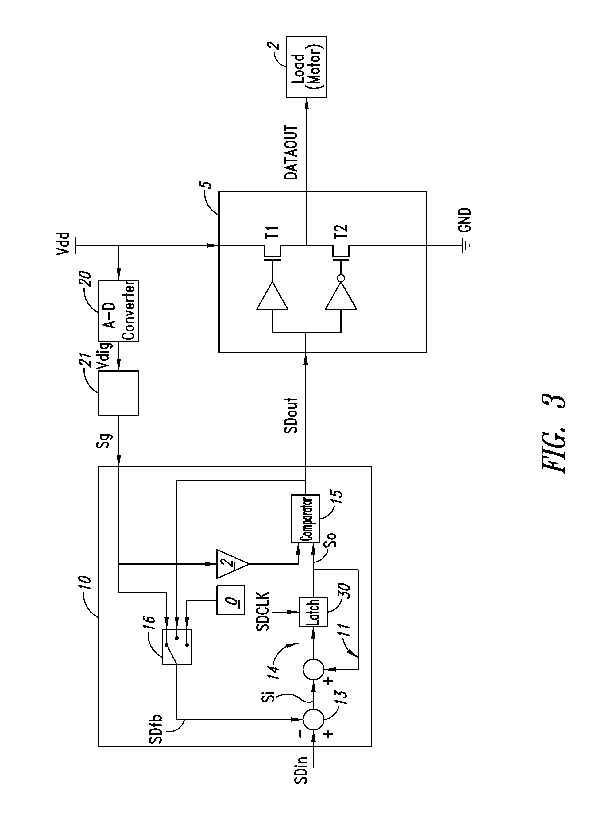
[0008]In view of the state of the art, the present disclosure provides a control apparatus for a supply device for a load, of less circuit complexity than the known apparatuses, and minimizing the use of semiconductor chip area.

Problems solved by technology

However, in the majority of cases there are considerable variations in the supply voltage Vdd.
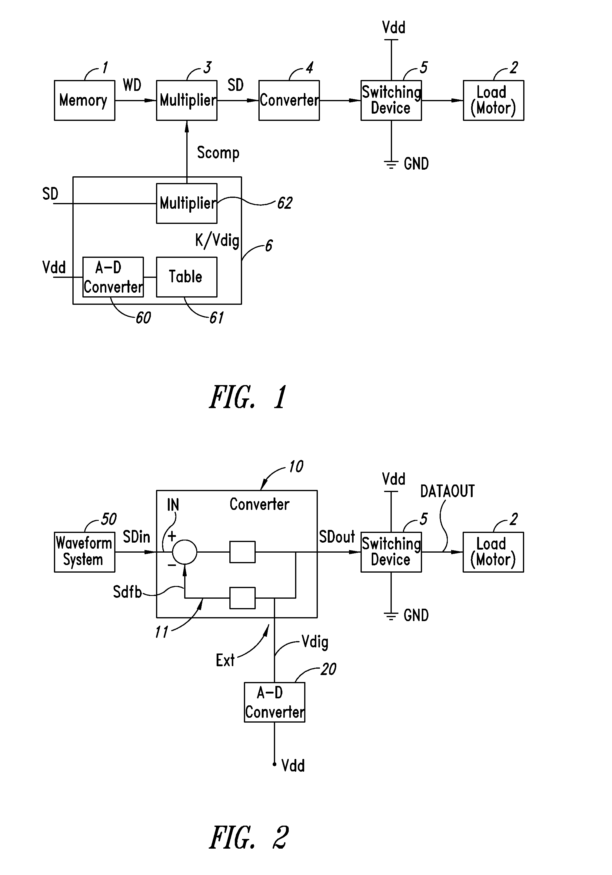
The two solutions for making the block 61 are costly in terms of the digital resources required, given that a large occupation of silicon area is necessary in the integrated circuits.

Method used


Image

  • Control apparatus for a load supply device
  • Control apparatus for a load supply device
  • Control apparatus for a load supply device

Examples


Embodiment Construction

[0026]In the following description, certain specific details are set forth in order to provide a thorough understanding of various disclosed embodiments. However, one skilled in the relevant art will recognize that embodiments may be practiced without one or more of these specific details, or with other methods, components, materials, etc. In other instances, well-known structures or components or both associated with motors and switching devices, including but not limited to coils, rotors, stators, and well-known components thereof have not been shown or described in order to avoid unnecessarily obscuring descriptions of the embodiments.

[0027]Unless the context requires otherwise, throughout the specification and claims that follow, the word “comprise” and variations thereof, such as “comprises” and “comprising” are to be construed in an open inclusive sense, that is, as “including, but not limited to.” The foregoing applies equally to the words “including” and “having.”

[0028]Refer...


PUM


Abstract

A control apparatus for a supply device of a load, the supply device is of switching type and connected between a supply voltage and a reference voltage, the apparatus including a sigma-delta device having an input terminal at which is present a first digital signal and adapted to provide a pulse-density modulation signal at the output terminal; the sigma-delta device including a feedback circuit capable of sending to the input terminal of the sigma-delta device a second digital signal whose value depends on the value of the output signal, and the apparatus including a device capable of digitalizing the supply voltage and of providing a further digital signal. The feedback circuit includes a terminal capable of receiving the further digital signal, and the sigma-delta device having a gain such that the output digital signal is proportional to the inverse of the further digital signal.

Description

BACKGROUND[0001]1. Technical Field[0002]The present disclosure refers to a control apparatus for a load supply device.[0003]2. Description of the Related Art[0004]Control apparatuses are currently known for motors of the digital type, such as the one illustrated in FIG. 1. FIG. 1 shows a memory 1 where waveform samples WD are stored for driving a load 2, for example a load formed by the series of a resistance and an inductance. The samples WD are multiplied in amplitude by means of a digital multiplier 3, and the resulting modulated digital signals SD are inputs to a PWM digital converter 4 capable of providing pulse-width modulation signals for driving the switching device 5; the latter is connected between a supply voltage Vdd and ground GND and is responsible for supplying the motor 2.[0005]In such control devices, the case where the average value of the signal at the output from the switching device 5 reflects the average value of the signal at the output of the PWM converter 3 ...

Claims


Application Information

Patent Timeline
Patent Type & Authority Patents(United States)
IPC IPC(8): H03M3/00
CPCH03M1/0845H03M3/324H03M1/822H03M3/506
Inventor MAIOCCHI, GIUSEPPE
Owner STMICROELECTRONICS SRL
Learn More