Eureka AIR delivers breakthrough ideas for toughest innovation challenges, trusted by R&D personnel around the world.

Cage free nest

a cage-free, nest technology, applied in the field of cage-free nests, can solve the problems of not providing comfort features for birds, squared edges or become slippery, and the house manager cannot inspect the nest belt, etc., and achieves the effect of minimal build-up of moisture and other materials

Inactive Publication Date: 2011-09-13
CTB INC
View PDF33 Cites 3 Cited by
  • Summary
  • Abstract
  • Description
  • Claims
  • Application Information

AI Technical Summary

Benefits of technology

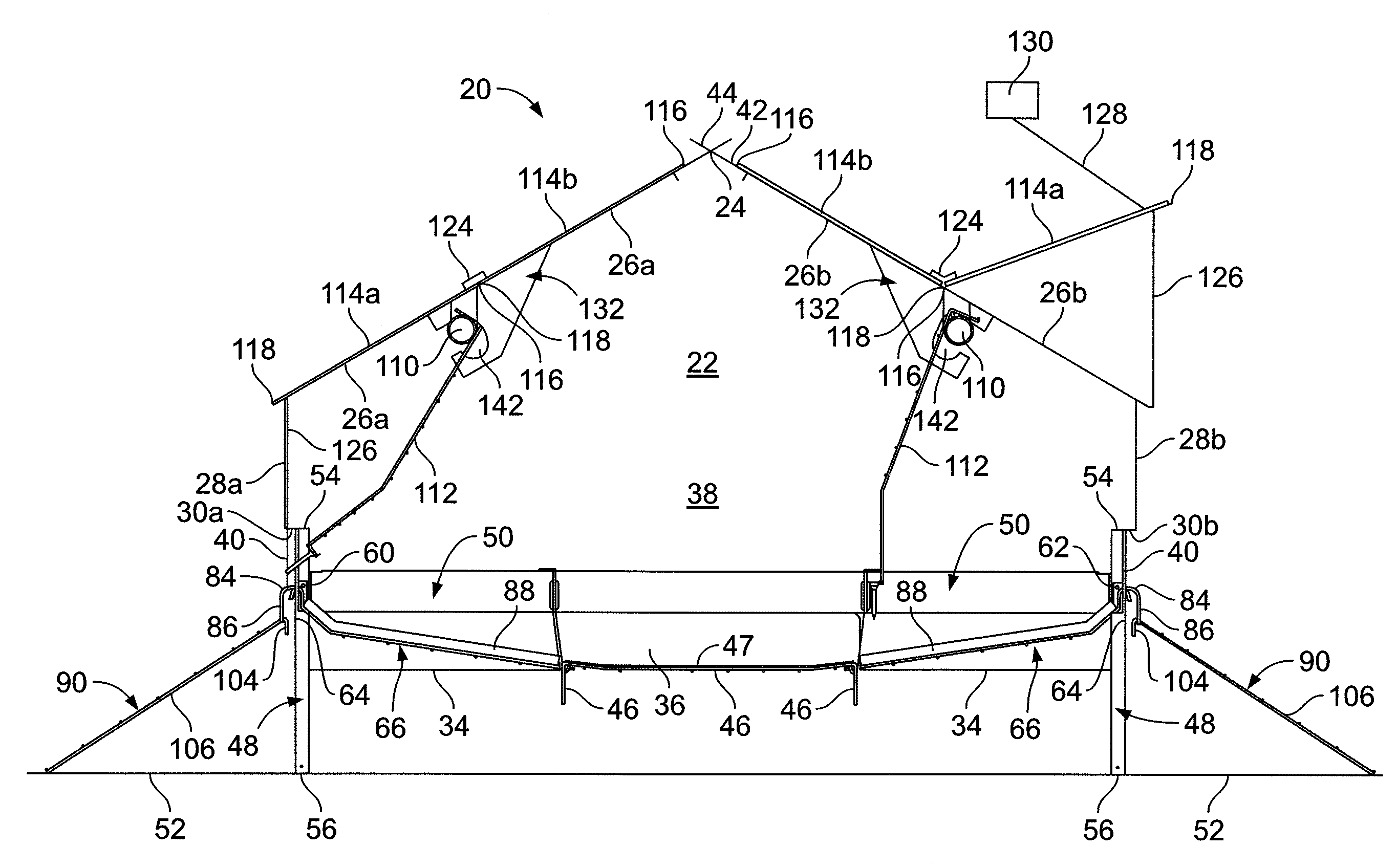
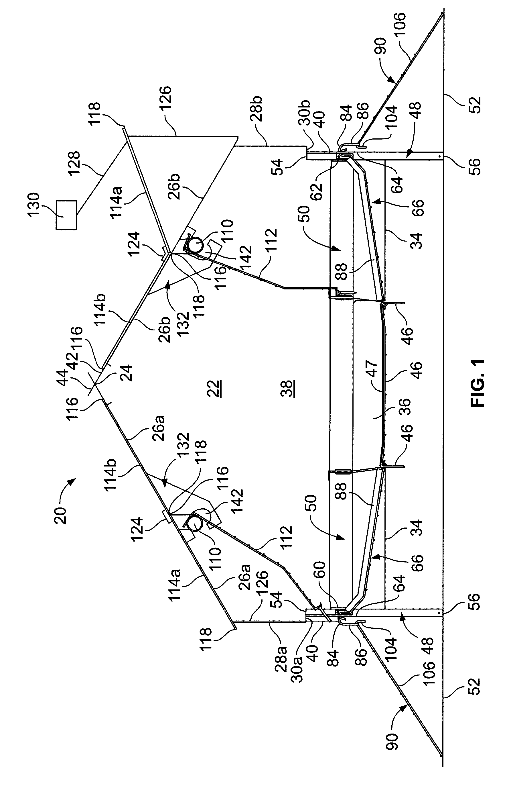
[0005]Briefly, and in accordance with the foregoing, the invention provides a novel cage free nest. The cage free nest has nest bottoms configured to have rounded / raised portions at the entranceways to the cage free nest such that a bird can step on the rounded / raised portions while entering and exiting the nesting area. The nest bottoms and the ramps leading to the entranceways from the surface below are formed of a non-slip, woven galvanized steel wire which allows for the birds to grip the nest bottoms and the ramps easily, even in the event that the nest bottoms and ramps have moisture or other materials built-up thereon. The build-up of moisture and other materials is also minimal because of the openings provided through the woven steel wire.

Problems solved by technology

For instance, these prior art cage free nests do not provide comfort features for birds when walking into the cage free nests as the entrance to the cage free nests can, for instance, have squared-off edges or become slippery in view of the materials used, for example wood.
These prior art cage free nests also do not have tops which allow a house manager to inspect the nest without having to remove the tops or hold back the curtains.
The house manager also cannot inspect the egg belt without having to holdup the nest top or remove it altogether.
Further, the tops on prior art cage free nests are prone to falling into the nest, which can possibly cause harm to the birds therein, if the tops or other parts of the cage free nests are bumped or misaligned.

Method used


Image

  • Cage free nest
  • Cage free nest
  • Cage free nest

Examples


Embodiment Construction

[0016]While this invention may be susceptible to embodiment in different forms, there is shown in the drawings and will be described herein in detail, a specific embodiment with the understanding that the present disclosure is to be considered an exemplification of the principles of the invention, and is not intended to limit the invention to that as illustrated and described herein.

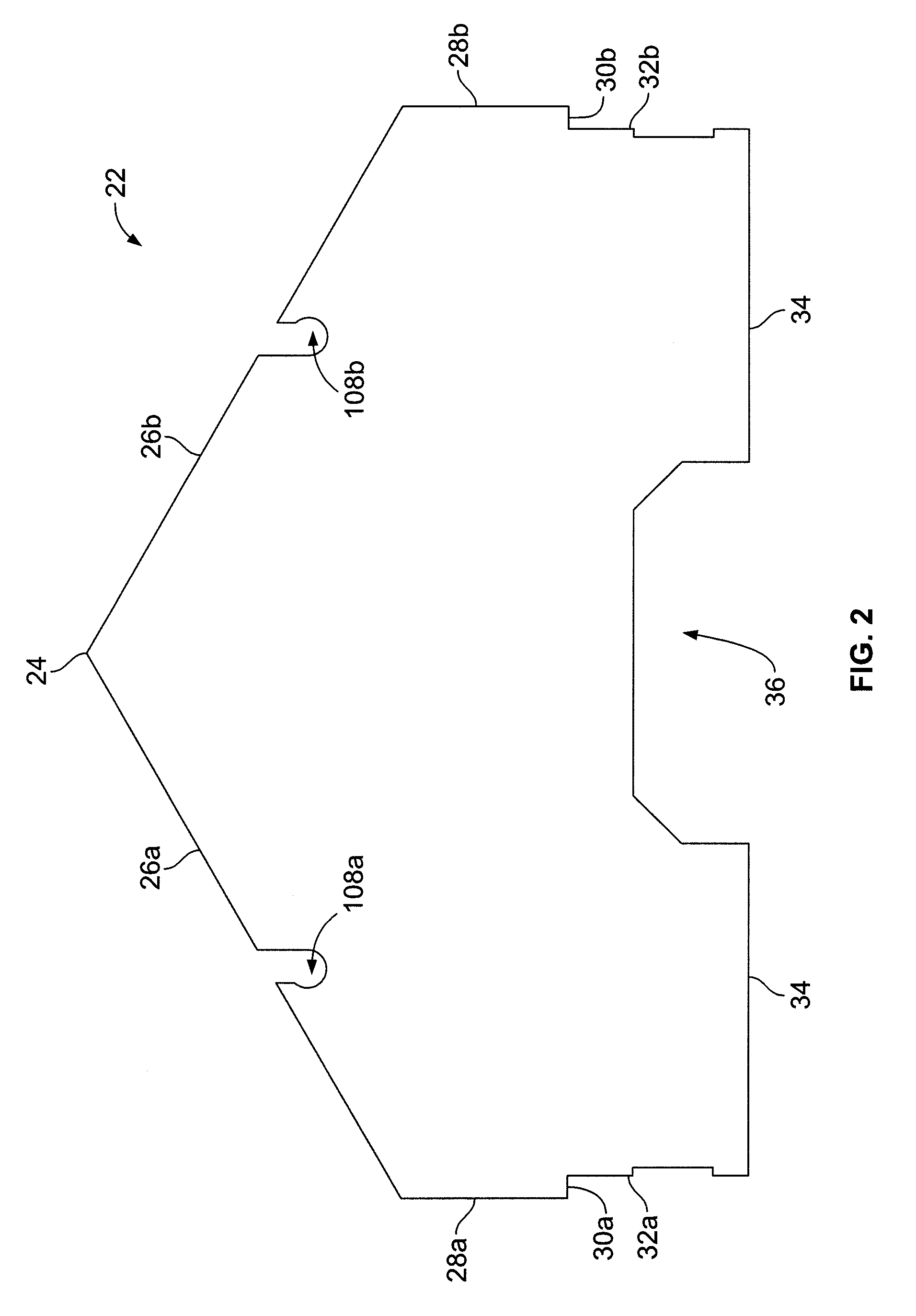
[0017]An embodiment of a cage free nest 20 of the present invention is illustrated in FIGS. 1-8 and will be described with reference thereto. The cage free nest 20 is configured to be positioned side-by-side another like cage free nest 20 in order to form a cage free nest assembly (not shown). Such a cage free nest assembly may have a plurality of like cage free nests 20 positioned side-by-side within a poultry house (not shown). Each cage free nest 20 is formed of a pair of sidewalls 22 (only one of which is shown) which are separated from one another by a predetermined distance. Each sidewall 22 has tw...


PUM


Abstract

A cage free nest has nest bottoms that have raised / rounded portions proximate to the entranceways into the cage free nest. A ramp extends from a surface to connect to the nest bottoms proximate to the entranceway. Both the nest bottoms and the ramp are formed of a non-slip, woven galvanized steel wire. The cage free nest also has upper and lower top panels that make up a roof assembly of the cage free nest. The lower top panels can be moved relative to the upper top panels to an opened / raised position by a cable assembly to allow for visual inspection into the cage free nest through the entranceways. The upper top panels can be moved relative to the lower top panels to an opened / raised position to allow for visual inspection into the cage free nest through the roof assembly.

Description

CROSS-REFERENCE AND INCORPORATION BY REFERENCE[0001]This patent application claims the benefit of domestic priority of U.S. Provisional Application Ser. No. 60 / 886,128, filed Jan. 23, 2007, and entitled “Rear Egg Roll-Out Commercial Cage Free Nest”. U.S. Provisional Application Ser. No. 60 / 886,128 is hereby incorporated by reference.FIELD OF THE INVENTION[0002]The present invention generally relates to cage free nests. More specifically, the present invention relates to rear egg roll-out commercial cage free nests.BACKGROUND OF THE INVENTION[0003]Rear egg roll-out commercial cage free nests are well-known in the art, but suffer from a number of disadvantages. For instance, these prior art cage free nests do not provide comfort features for birds when walking into the cage free nests as the entrance to the cage free nests can, for instance, have squared-off edges or become slippery in view of the materials used, for example wood. These prior art cage free nests also do not have tops ...

Claims


Application Information

Patent Timeline
Patent Type & Authority Patents(United States)
IPC IPC(8): A01K31/16
CPCA01K31/16
Inventor DOWTY, LARRY D.
Owner CTB INC
Why Eureka
Eureka Blog
Learn More