
Fast roaming system

Active Publication Date: 2011-08-16
NEC CORP
View PDF26 Cites 10 Cited by
  • Summary
  • Abstract
  • Description
  • Claims
  • Application Information

AI Technical Summary

Benefits of technology

[0021]To resolve these problems, it is one objective of the present invention to provide a fast roaming system for selecting a roaming destination AP providing a better operating environment within a sort period of time, and for increasing the roaming completion ratio.
[0022]According to the present invention, a fast roaming system is a system whereby a mobile terminal while communicating with an access point, serving as a parent station, over a wireless LAN that conforms to the IEEE 802.11 specifications, can be quickly switched from the parent station to an adjacent access point having an overlapping communication range.
[0036]As described above, the fast roaming system of the invention, wherein a search for the access points is not performed during the roaming operation, comprises a variety of units that can rapidly and exactly perform the selection of an access point providing a better wireless environment and the connection of the access point at a higher roaming completion ratio.

Problems solved by technology

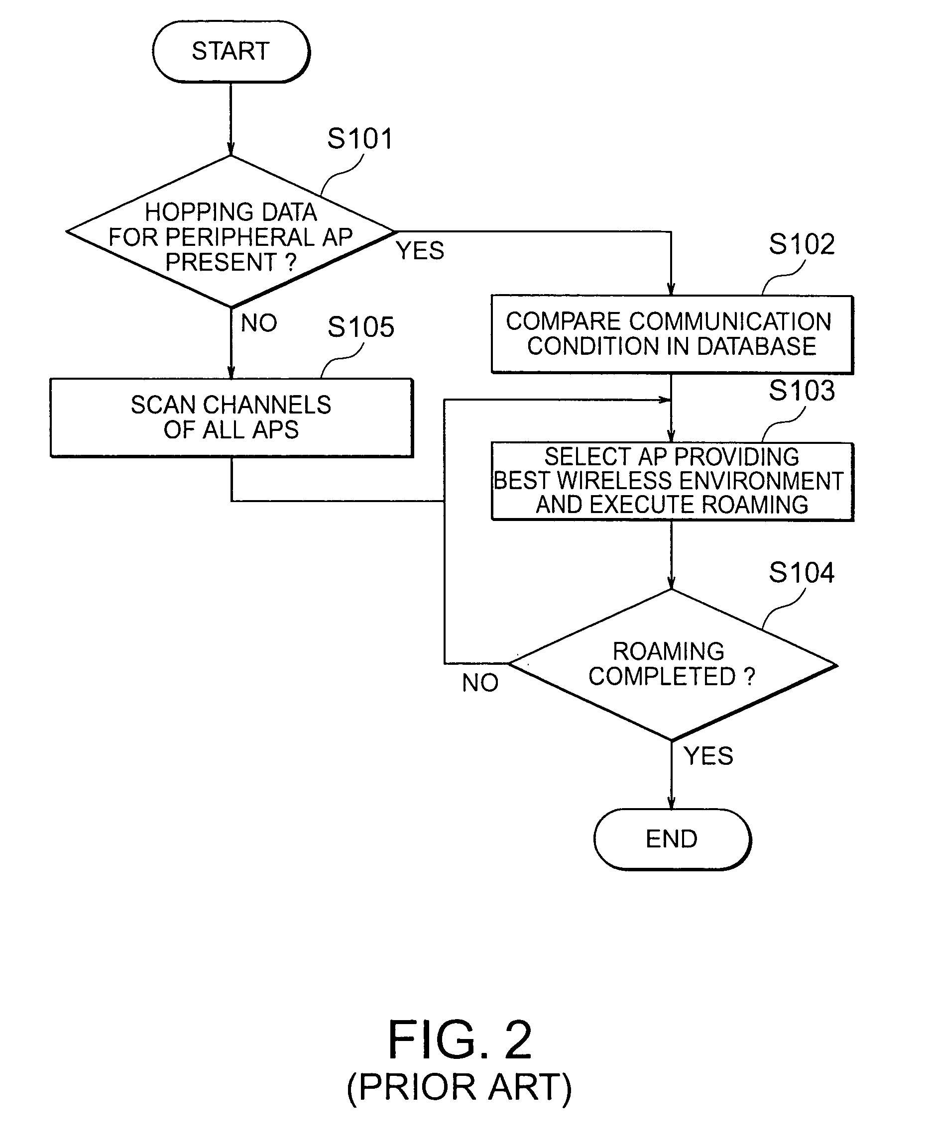
Accordingly, it is unfavorable that, for the mobile terminal, the database contents used when selecting a roaming destination AP frequently differ from the current ones.
Further, in the conventional fast roaming system described above, the AP data collected by each AP is limited to that for APs located around the periphery of the pertinent AP and that the thus collected data include no condition information that indicate whether a mobile terminal can be connected.
Therefore, it is unfavorable that there is high probability that a connection-disabled AP will be selected as a roaming destination AP by the mobile terminal.

Method used


Image

  • Fast roaming system
  • Fast roaming system
  • Fast roaming system

Examples


Embodiment Construction

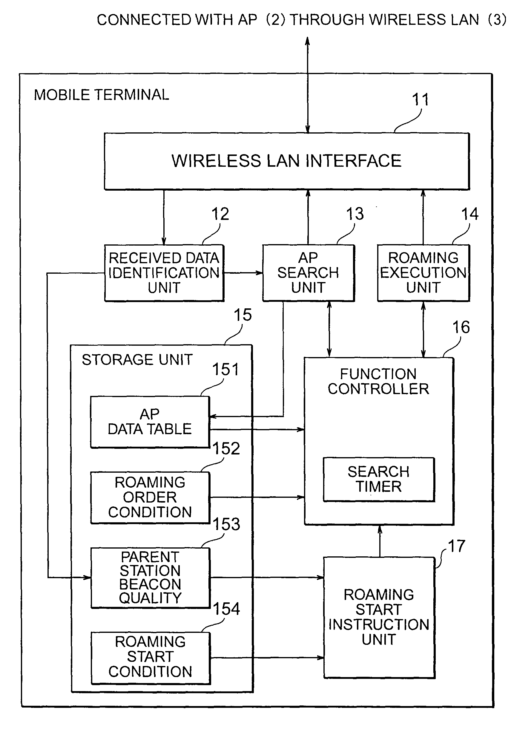
[0064]The preferred embodiment of the present invention will now be described while referring to the accompanying drawings. In these drawings, the functional blocks according to the present invention are simplified and shown to help in the understanding of the explanation.

[0065]FIG. 3 is a basic diagram showing the connection of functional blocks according to one embodiment of the present invention. A fast roaming system in FIG. 3 includes a mobile terminal 1, access points (hereinafter referred to simply as APs) 2 including a parent station AP 2-A, and peripheral APs 2-B, . . . , for which communication areas 4 overlap. The mobile terminal 1 is a mobile terminal for communication. The parent station AP 2-A is currently communicating with the mobile terminal 1. The peripheral APs 2-B, . . . , are located near the mobile terminal 1. More than one of these components is provided, and for the mobile terminal 1, the type is not limited to that of a mobile terminal.

[0066]The mobile termi...


PUM


Abstract

A fast roaming system for changing, in a short period of time, the connection to a roaming destination AP (access point) providing a better communication environment, and for improving a roaming completion rate. In response to a search process performed by a mobile terminal, individual APs transmits AP data required for roaming directly to the mobile terminal. The mobile terminal performs the passive scanning search or the active scanning search for the peripheral APs at short time intervals, and obtains and stores the latest AP data in an AP data table. As a result, only the latest data for the connectable peripheral AP can be stored as a roaming destination in the AP data table. Furthermore, since the order condition is set by the mobile terminal to select the roaming destination AP, there is a high probability that the roaming is completed when the peripheral AP is first selected. Therefore, only a short period of time is required until the roaming is completed.

Description

BACKGROUND OF THE INVENTION[0001]The present invention relates to a fast roaming system whereby a mobile terminal, while communicating with an access point, serving as a parent station, over a wireless LAN that conforms to the IEEE 802.11 specifications developed by the Institute of Electrical & Electronics Engineers (IEEE), can be quickly switched from the parent station to an adjacent access point having an overlapping communication range. The present invention relates in particular to a fast roaming system wherein, without communication being interrupted, a roaming destination access point providing better environmental conditions can be selected and a roaming completion ratio improved, and wherein a fast roaming operation can be effectively performed under a variety of conditions.[0002]Generally, the IEEE 802.11 specifications, which constitute a well known wireless LAN technique, are typically applied for a wireless LAN.[0003]There are two types of wireless LANs: one is a so-ca...

Claims


Application Information

Patent Timeline
IPC IPC(8): H04W4/00H04J3/06H04L12/28H04W28/00H04W36/12H04W36/36H04W48/20H04W84/12H04W88/08
CPCH04W36/08H04J3/0641H04W84/12
Inventor TSUTSUMI, TAKAYUKIKOBAYASHI, YOSHIKAZU
Owner NEC CORP
Learn More