
Birdcage-like transmitting antenna for MRI

a technology of transmitting antenna and bird cage, which is applied in the direction of magnetic measurement, instruments, measurement devices, etc., can solve the problem of design of transmitting antennas that cannot be detachable, and achieve the effect of a larger cross-section

Inactive Publication Date: 2011-08-02
SIEMENS AG
View PDF18 Cites 135 Cited by
  • Summary
  • Abstract
  • Description
  • Claims
  • Application Information

AI Technical Summary

Benefits of technology

"The present invention is about a transmission antenna for magnetic resonance applications that can deliver a high-quality radio-frequency transmission field even when examining asymmetrical subjects and in the presence of larger static magnetic fields. The antenna has multiple antenna rods that are distributed around a central axis and are terminated at their first and second ends by a first and second ferrule elements, respectively. A detuning circuit is located at the side of the antenna to fine-tune its resonance frequency. The antenna rods are surrounded by a radio-frequency shield to optimize the quality of the transmission field. The distance between the antenna rods and the shield is different to achieve a uniform field. The second terminating element has a larger cross-section than the first one. The antenna can be designed as a whole-body or a head coil and can be tuned to any resonance frequency. The detuning circuit includes PIN diodes. The conductors for feeding and conducting signals are advantageously arranged on the side of the second terminating element."

Problems solved by technology

Among other things, the requirement to design the transmission antennas to be detunable results due to the use of separate transmission and reception antennas.

Method used


Image

  • Birdcage-like transmitting antenna for MRI
  • Birdcage-like transmitting antenna for MRI
  • Birdcage-like transmitting antenna for MRI

Examples


Embodiment Construction

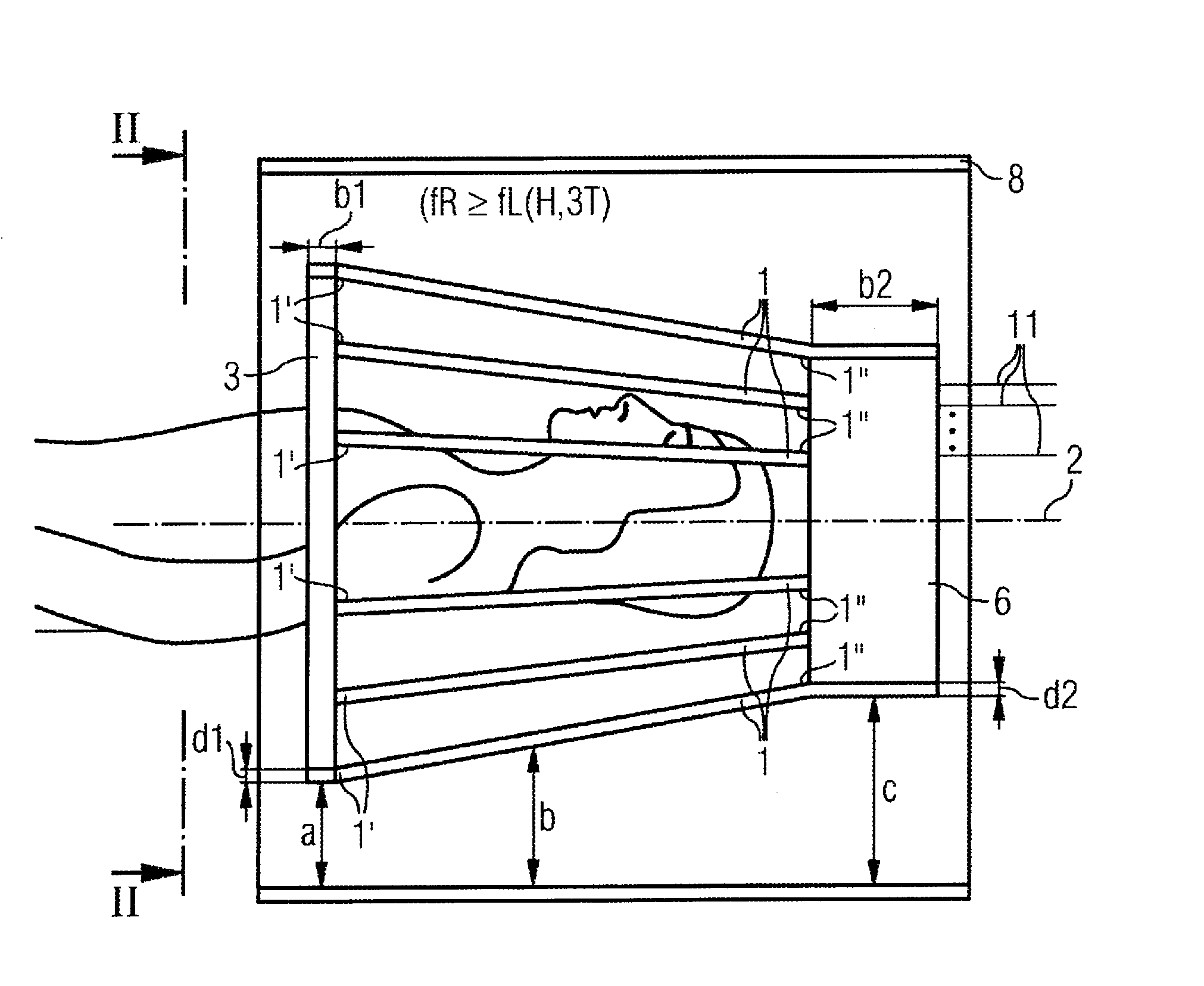
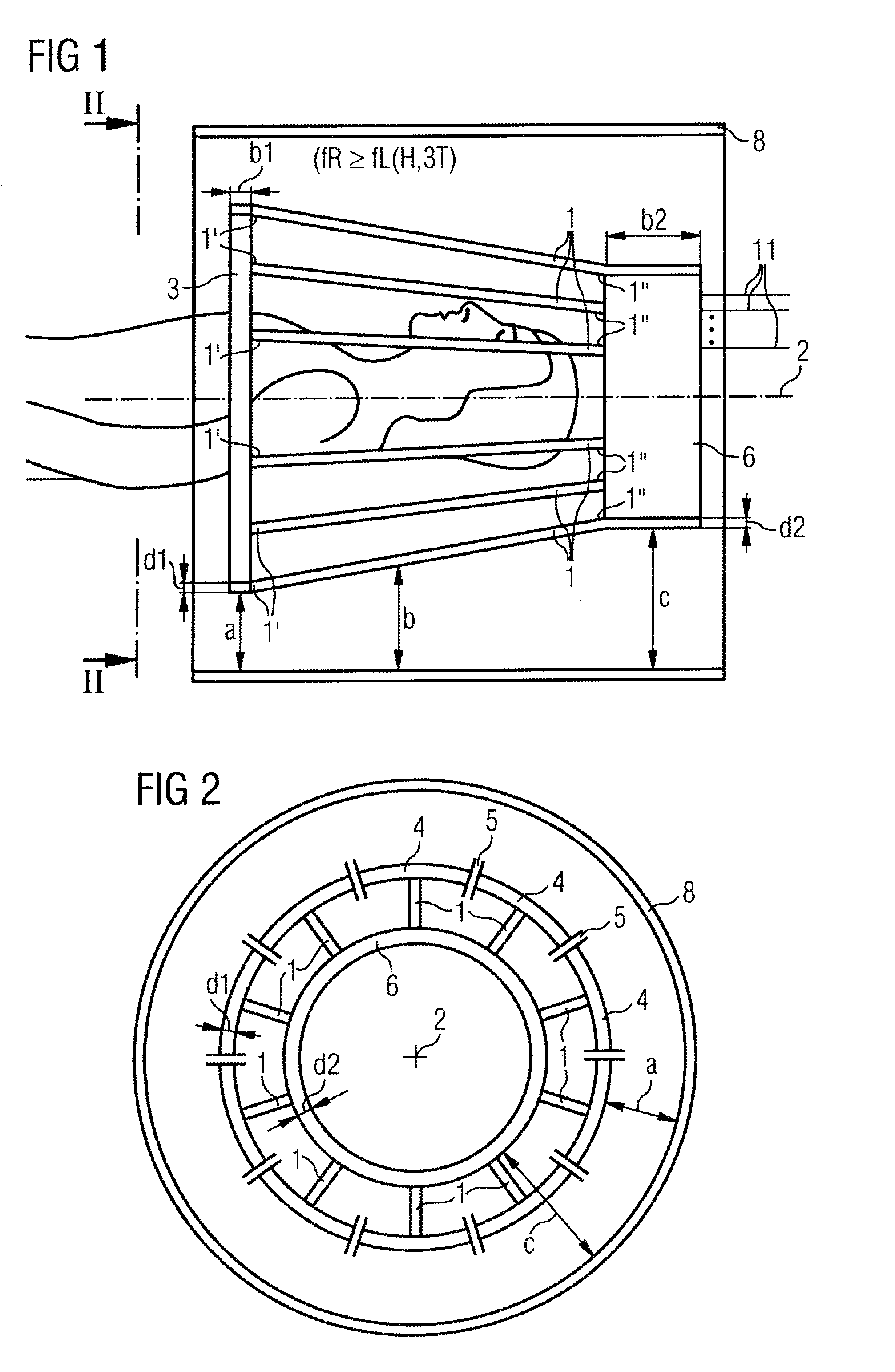
[0021]According to FIGS. 1 and 2, a transmission antenna for magnetic resonance applications possesses a number of antenna rods 1. Each antenna rod 1 extends from a first end 1′ to a second end 1″ of the respective antenna rod 1.

[0022]In a preferred embodiment, the antenna rods 1 run (at least essentially) parallel to a central axis 2. The number of antenna rods 1 is at minimum 4. There are normally 16 or 32. However, other numbers of antenna rods 1 are also possible, for example 6, 8, 12, 24 or 40 antenna rods 1.

[0023]In the illustrated normal case, the antenna rods 1 run exactly parallel to the central axis 2. However, alternative embodiments are possible in which the antenna rods 1 define a direction that is only essentially parallel to the central axis 2. In this latter cited case, the respective antenna rod 1 exhibits a direction that possesses a first partial component and a second partial component. The two partial components complement the direction of the respective rod axi...


PUM


Abstract

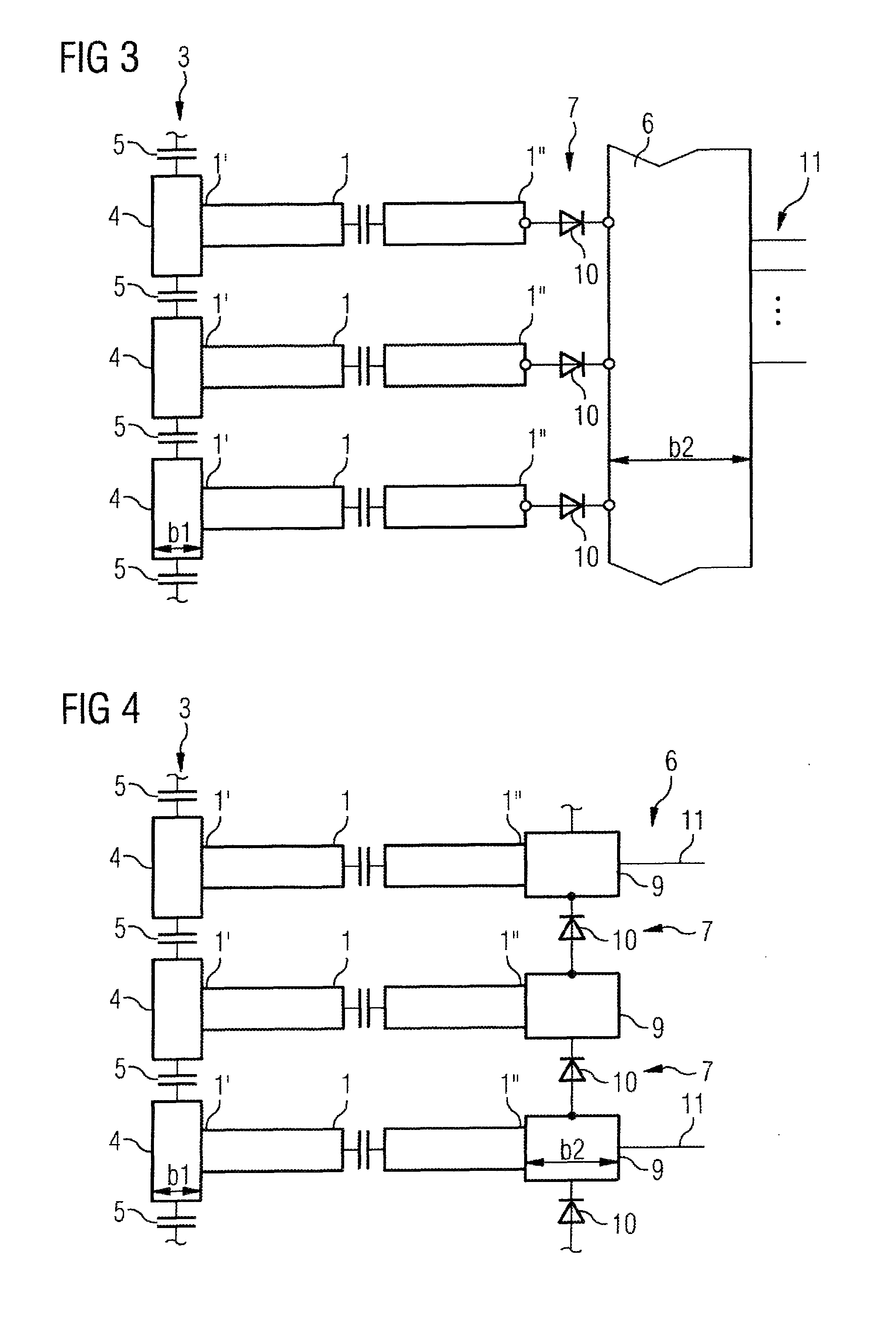
A transmission antenna for magnetic resonance applications has a birdcage-like structure that includes antenna rods proceeding between first and second terminating elements respectively located at opposite ends of the antenna rods. A detuning circuit is located at the second terminating element. Either the second terminating element is formed as a completely continuous short circuit ring and the detuning circuit is arranged between the ends of the antenna rods and the second terminating element, or the second terminating element has a number of ferrule segments, between which the detuning circuit is arranged. The second terminating element has a larger cross-section than a the first terminating element.

Description

BACKGROUND OF THE INVENTION[0001]1. Field of the Invention[0002]The present invention concerns a transmission antenna for magnetic resonance applications of the type having a basic configuration known as a “birdcage” antenna.[0003]2. Description of the Prior Art[0004]In magnetic resonance imaging, transmission and reception antennas separated from one another are used, in particular in the head area. The antennas are typically also designated as coils. Among other things, the requirement to design the transmission antennas to be detunable results due to the use of separate transmission and reception antennas.[0005]In the prior art, transmission antennas are normally fashioned as birdcage resonators. They therefore always have two ferrules as terminating elements, wherein the ferrules are fashioned identically. In particular, the ferrules are composed of ferrule segments that are coupled with one another via ferrule capacitors. In individual cases, antennas known as TEM resonators ar...

Claims


Application Information

Patent Timeline
Patent Type & Authority Patents(United States)
IPC IPC(8): G01V3/00
CPCG01R33/34046G01R33/34076G01R33/3657G01R33/422G01R33/3642
Inventor LAZAR, RAZVANRENZ, WOLFGANG
Owner SIEMENS AG
Learn More