
Umpire counter with null indicators

a technology of indicators and umpires, applied in the field of umpire counters, can solve problems such as disrupting the rhythm of the gam

Active Publication Date: 2011-06-28
HICKOX EDWIN W
View PDF17 Cites 7 Cited by
  • Summary
  • Abstract
  • Description
  • Claims
  • Application Information

AI Technical Summary

Problems solved by technology

However, this can disrupt the rhythm of the game.

Method used


Image

  • Umpire counter with null indicators
  • Umpire counter with null indicators
  • Umpire counter with null indicators

Examples


first embodiment

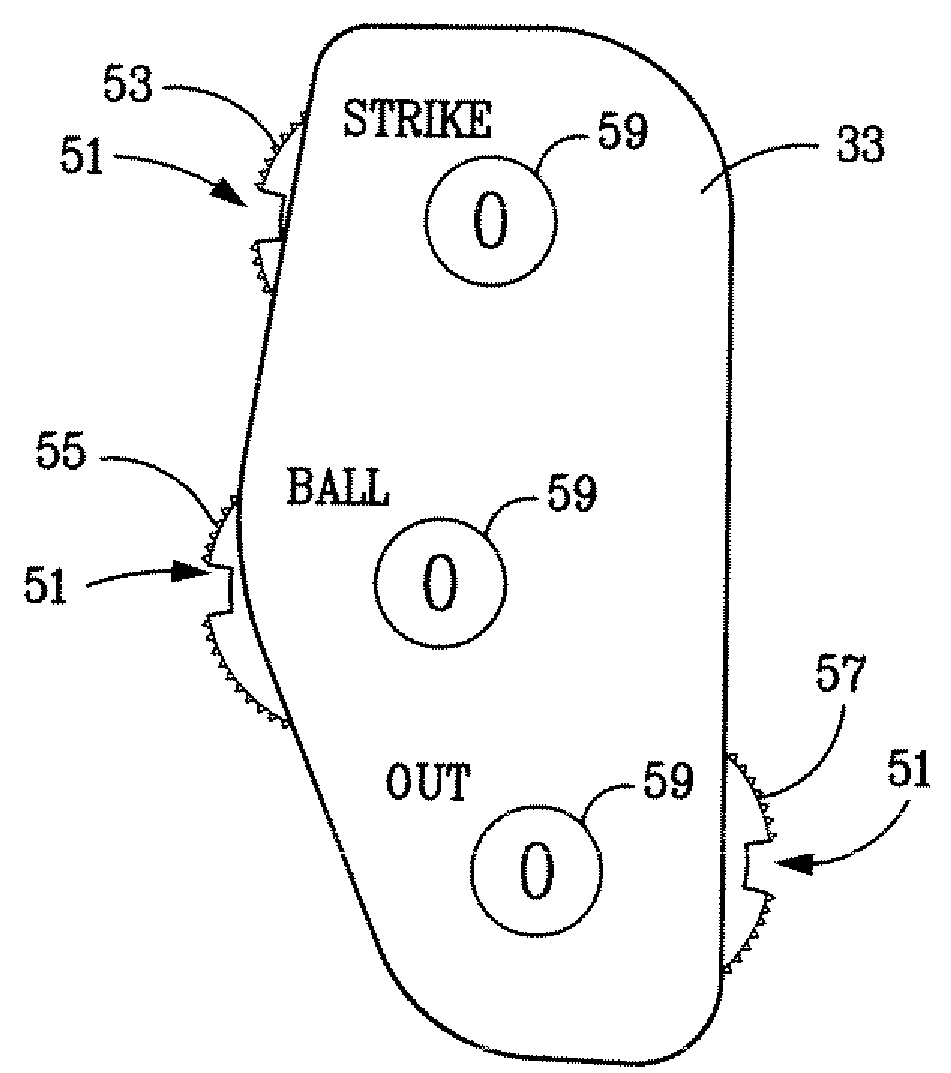
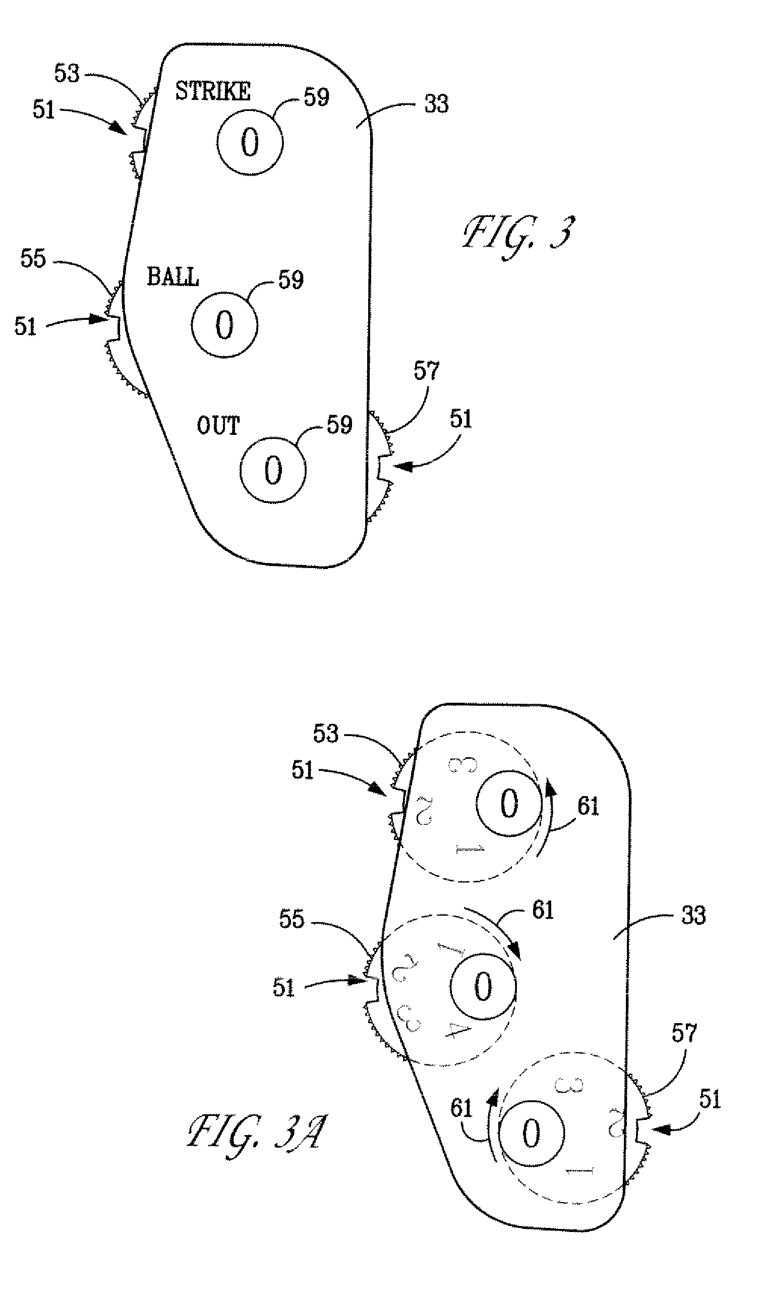
the invention, FIGS. 3-8a, has a single, smooth-walled, large notch 51 having an absence of serrations and extending into the circumferential edge of each round disk-shaped counter dial 53, 55 and 57, FIGS. 3 and 3a. Each of the notched dials 53, 55, 57 is about one inch in diameter and carries an otherwise serrated circumferential edge. For a dial 53, 55, 57 which is about one inch in diameter, each notch is about 1 / 16 inch deep and about ⅛ to 3 / 16 inches wide at its “mouth”, wherein each notch 51 has an arc width of about 15 to 20 circular degrees. Each of the notched dials 53 and 57 carries numbers on its front face from “0” to “3”, FIGS. 3a and 7a. The notched dial 55 carries numbers on its front face from “0” to “4”.

Each of the dials 53, 55, and 57 has its numbers spaced evenly around the periphery of its top face, FIGS. 7a, 7b and 8a in “merry-go-round” fashion. The numbers on each dial 53, 55, 57 are viewable through the top face of the counter case through a respective round...


PUM


Abstract

A handheld, thumb or finger operated, umpire's counter having three dials to indicate the count kept by the umpire for each of “strikes”, “balls”, and “outs”. Each dial has associated with it a null indicator having a tactile output perceptible to the touch. This tactile output enables the umpire to determine when the respective dial is set to “0”, or to set and / or reset a respective dial to “0” without looking at the counter. It also permits the umpire to confirm that each dial is indeed set to “0” before he begins counting.

Description

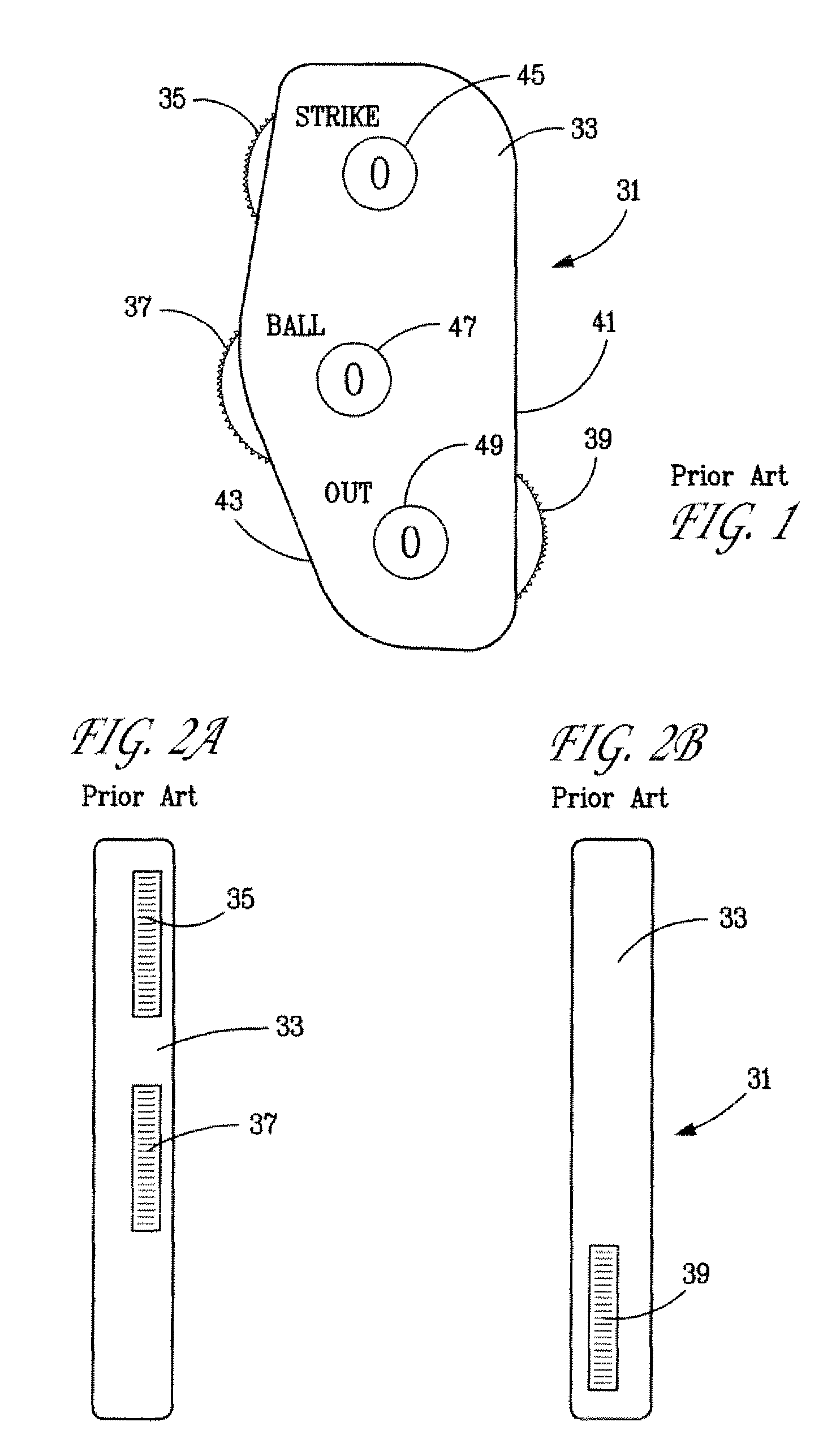
BACKGROUND OF THE INVENTIONThe present invention relates to sports umpire counters, also called umpire indicators. Home plate umpires, during a game of baseball, or softball, are responsible for keeping track of the number of “strikes” and “balls” on a batter and the number of “outs” in an inning. Umpires and referees in other sports are also required to keep count of various events.Handheld counters have been used for this purpose. Generally, these counters have included a plurality of rotary dials which carry indicia on one face. This indicia is most commonly Arabic numerals, i.e., numbers, indicating the number of “strikes” from 0 to 3, the number of “balls” from 0 to 4, and the number of “outs” from 0 to 3.The numbers are spaced about the face of each dial to appear, individually, to be read in a viewing window when the dial is turned to indicate that number. The dials generally are indexed with detents to hold the dial at each number when the number is centered in the dial's vi...

Claims


Application Information

Patent Timeline
Patent Type & Authority Patents(United States)
IPC IPC(8): A63B53/14
CPCA63B71/0672A63B2071/0633A63B2243/0004A63B2220/17A63B2071/0655A63B2102/18A63B2102/182
Inventor HICKOX, EDWIN W.
Owner HICKOX EDWIN W
Learn More