Developer supply case and image forming apparatus
a technology of image forming apparatus and supply case, which is applied in the direction of electrographic process apparatus, packaging, instruments, etc., can solve the problems of developer supply, dirty operator and surroundings, and dirty interior, and achieve the effect of preventing false operation
- Summary
- Abstract
- Description
- Claims
- Application Information
AI Technical Summary
Benefits of technology
Problems solved by technology
Method used
Image


Examples
first embodiment
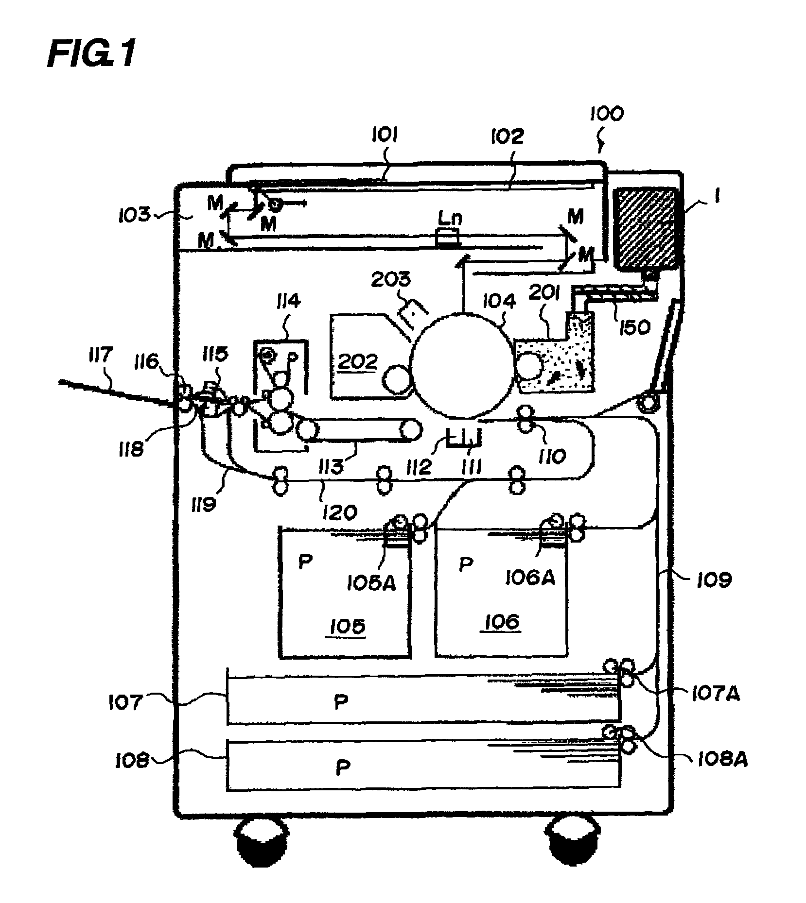
[0040]The constitution of an electrophotograph copying machine as an example of an image forming apparatus which employs electrophotography and has a developer supply case according to a first embodiment inserted thereinto will be described based on FIG. 1.
[0041][Overall Constitution of the Image Forming Apparatus]
[0042]In FIG. 1, in an electrophotograph copying apparatus body (hereinafter, called an “apparatus body”) 100, an original 101 is placed on a document glass 102 and a plurality of mirrors M and a lens Ln of an optical portion 103 are arranged in such a manner that image information is imaged on a photosensitive drum 104 as an image bearing member. Of sheets P stacked on sheet cassettes 105, 106, 107, and 108, the sheet which is most suitable for information input by the user from an operation portion (not illustrated) or the sheet size of the original 101 is selected according to the sheet size information of the sheet cassettes 105 to 108.
[0043]One of the sheets P conveye...
second embodiment
[0113]The apparatus according to the second embodiment will be described with reference to FIG. 19. The basic constitution of the apparatus of this embodiment is the same as that of the above embodiment and the overlapped description is omitted. The constitution as the feature of this embodiment will be described here. The members having the same functions as those of the above embodiment are indicated by similar reference numerals.
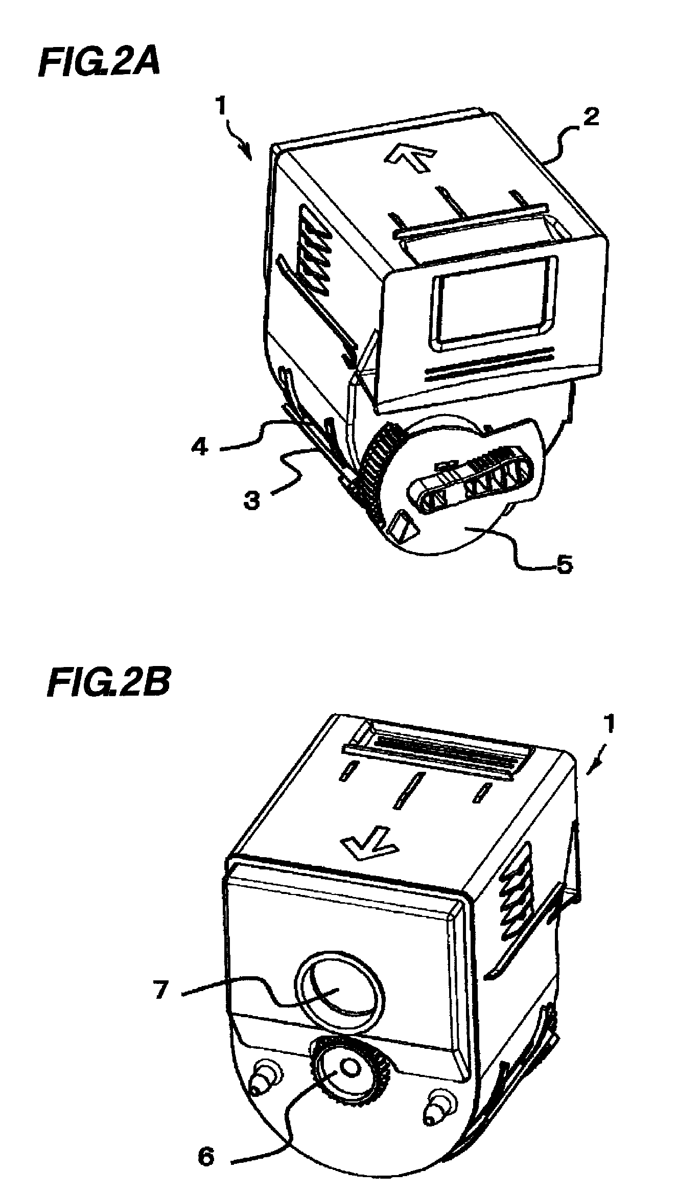
[0114]As in the first embodiment, the developer supply case 1 illustrated in this embodiment has the case body 2, the shutter 3, the packing material 4, the handle 5, the coupling 6, and the inside stopper 7.
[0115]The shutter 3 illustrated in this embodiment has a lock portion which regulates the position until the developer supply case 1 is inserted into the hopper 10.
[0116]The developer supply case 1 of this embodiment will be described using FIGS. 19A and 19B. FIG. 19A is a perspective view of the developer supply case 1 according to this embodiment, a...
third embodiment
[0123]In the above embodiment, the developer supply case is illustrated as the inserting member inserted into the inserted portion. The inserting member need not be limited to the developer supply case. Any inserting member which causes the inserting load by engagement immediately before it is completely inserted into the inserted portion is applicable. In this case, before engagement of the engaging portion, a load larger than that caused by the engagement is caused and the inserting load is set to be changed such that the user cannot feel the load at engagement of the engaging portion. The user cannot misunderstand the inserting completion before engagement of the engaging portion.
PUM
 Abstract
Description
Claims
Application Information
 - R&D
- Intellectual Property
- Life Sciences
- Materials
- Tech Scout
- Unparalleled Data Quality
- Higher Quality Content
- 60% Fewer Hallucinations
Browse by: Latest US Patents, China's latest patents, Technical Efficacy Thesaurus, Application Domain, Technology Topic, Popular Technical Reports.
© 2025 PatSnap. All rights reserved.Legal|Privacy policy|Modern Slavery Act Transparency Statement|Sitemap|About US| Contact US: help@patsnap.com