
Constrained motion bone screw assembly

a screw and screw head technology, applied in the field of spinal fixation devices, can solve the problems of screw shank movement in the plane in which movement is not desirable, and the screw shank movement relative to the screw head is not desirabl

Active Publication Date: 2011-05-31
SARL DEPUY SPINE +1
View PDF195 Cites 111 Cited by
  • Summary
  • Abstract
  • Description
  • Claims
  • Application Information

AI Technical Summary

Benefits of technology

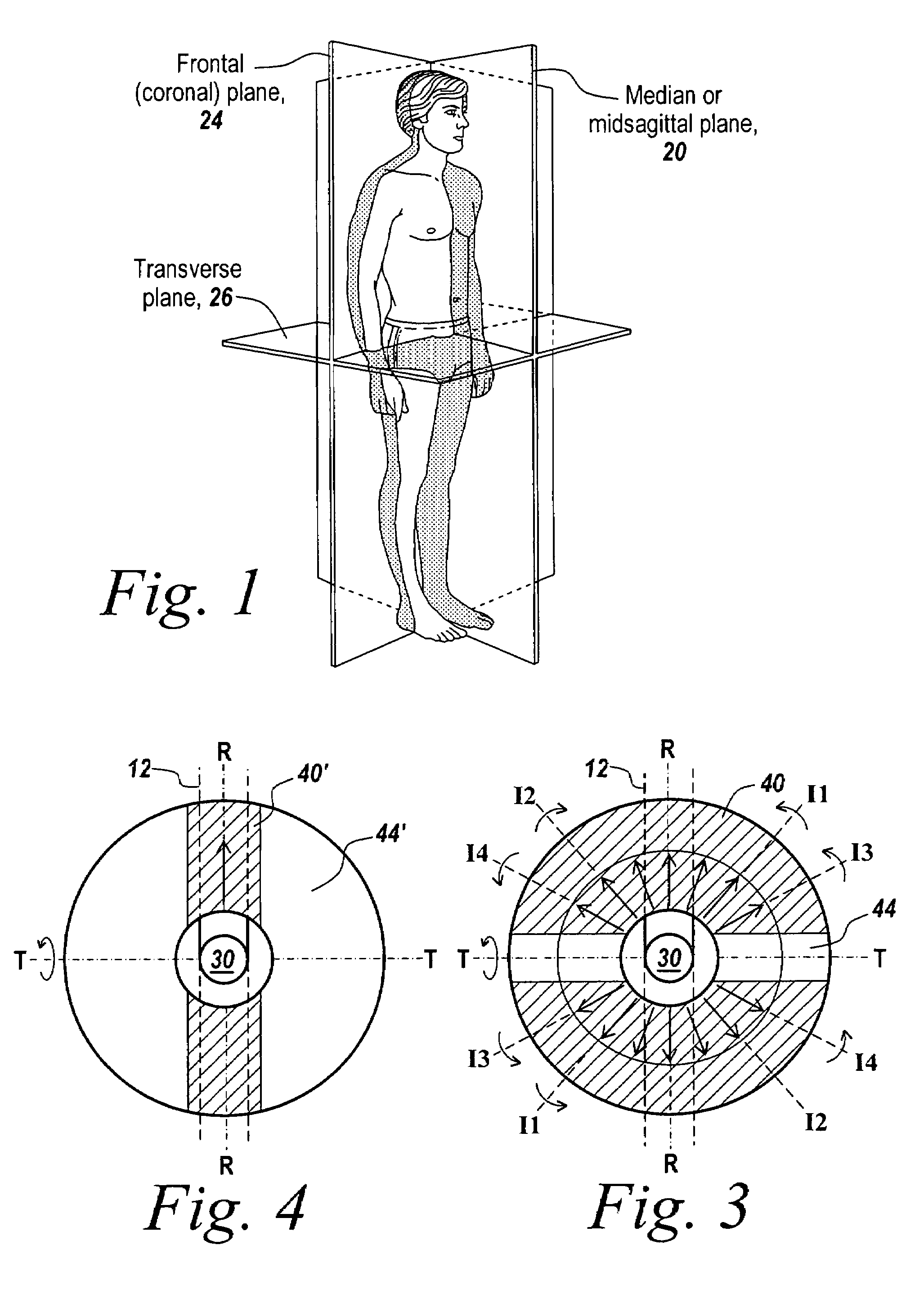
[0013]The proximal head may have at least one flat side surface to prevent pivoting of the bone anchor in the second direction.
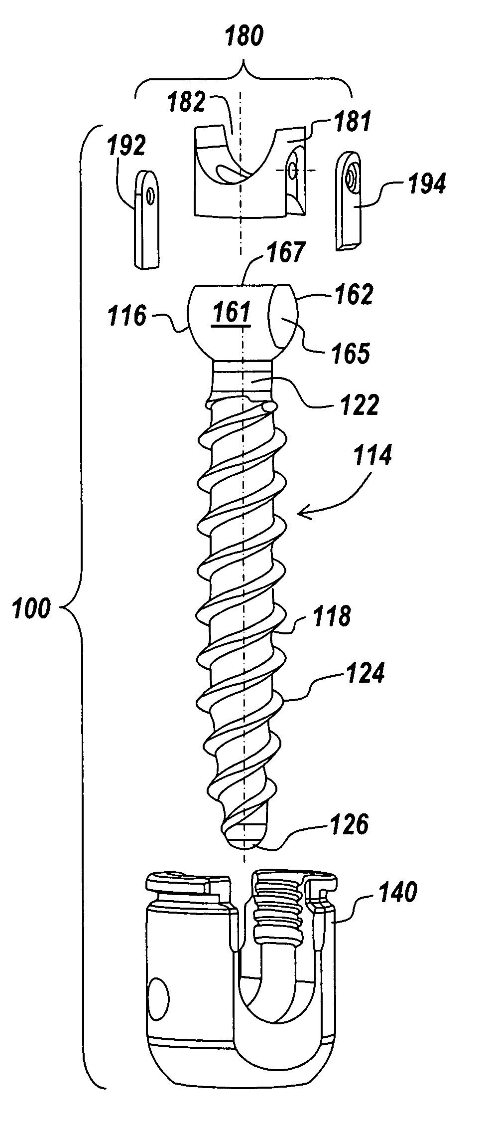
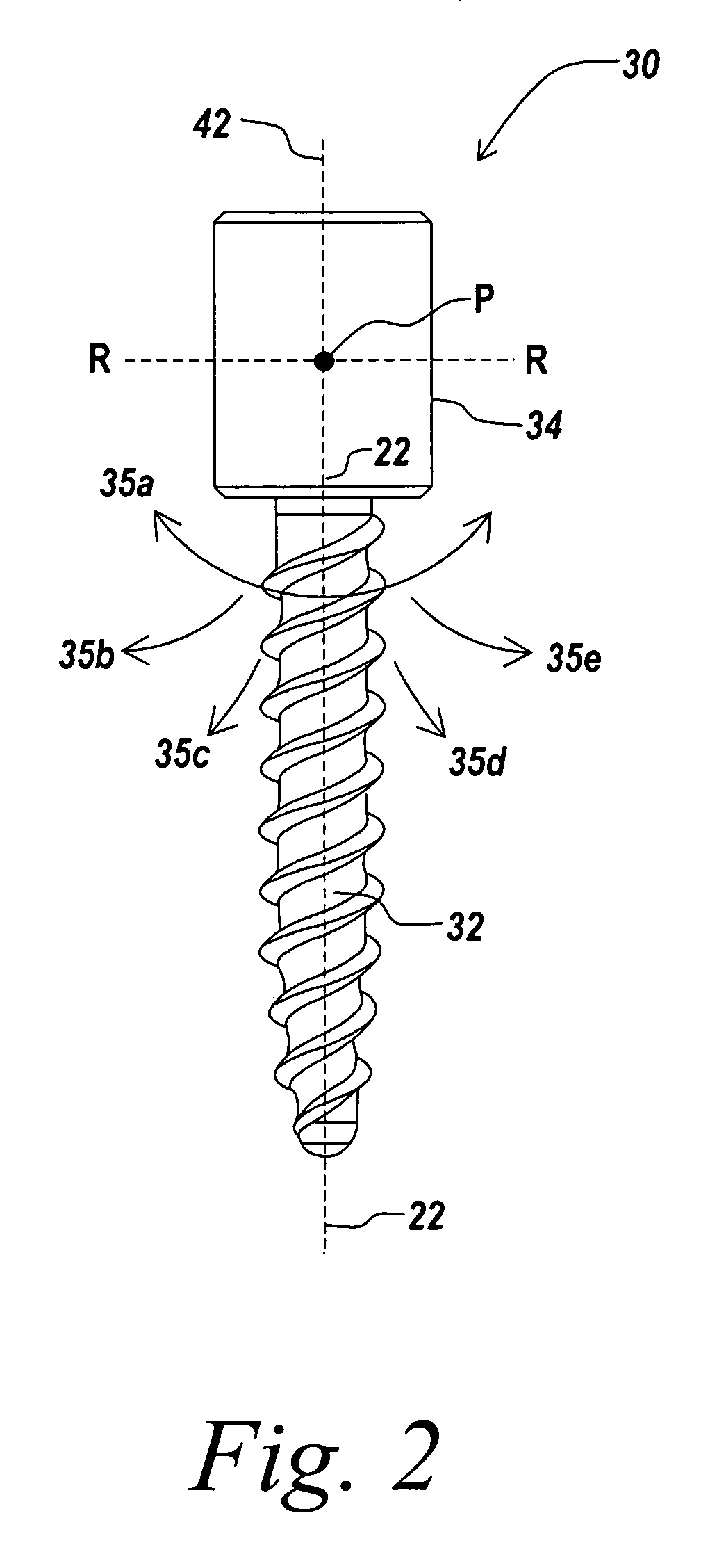
[0017]According to another aspect, a bone anchor assembly comprises a bone anchor having a distal shaft extending along a longitudinal axis configured to engage bone and a proximal head having at least one flat side surface extending substantially parallel to the longitudinal axis and a restriction member. The restriction member receives the proximal head on a first side and configured to mate with a first flat side surface of the proximal head to prevent pivoting of the distal shaft about a first axis of the proximal head that is parallel to the first flat side surface.
[0018]According to another aspect of the invention, a bone anchor assembly comprises a bone anchor having a distal shaft extending along a longitudinal axis configured to engage bone and a substantially spherical proximal head having at least one flat side surface extending substantially parallel to the longitudinal axis. A receiving member receives a spinal fixation element and movably engages the spherical proximal head. A restriction member is inserted in the receiving member for mating with the flat side surface of the anchor head to prevent rotation of the bone anchor relative to the receiving member in a direction that is perpendicular to the flat side surface.
[0020]According to still another aspect of the invention, a bone anchor assembly comprises a bone anchor having a distal shaft extending along a longitudinal axis configured to engage bone and a proximal head having at least one flat side surface extending substantially parallel to the longitudinal axis and a capping member configured to engage the proximal head on a first side and a spinal rod on a second side, the capping member including a first protrusion extending over and abutting a first flat side surface to prevent rotation of the distal shaft about a first axis of the proximal head that is parallel to the first flat side surface. The capping member may prevent the anchor portion from pivoting out of a plane aligned with the rod. The proximal head may be substantially spherical in shape.
[0023]According to another aspect of the invention, a bone anchor assembly includes a bone anchor having a distal shaft extending along a longitudinal axis configured to engage bone and a proximal head and a rod seat coupled to the bone anchor for seating a spinal rod. The rod seat allows for a relative pivoting movement between the bone anchor and a spinal rod inserted in the rod seat in at least a first direction, while restricting relative pivoting movement between the bone anchor and the spinal rod in a second direction. The rod seat may pivot relative to the bone anchor to facilitate pivoting of the bone anchor relative to the spinal rod. The bone anchor assembly may further comprise a receiving member coupled to the bone anchor for housing the rod seat. The rod seat may comprise a lower rod seat coupled to the receiving member and having a substantially spherical surface configured to slidably mate with a recess in the proximal head of the bone anchor and an upper rod seat pivotably connected to the receiving member, so that the lower rod seat and upper rod seat define therebetween a movable channel for receiving the spinal rod and for allowing relative movement between the bone anchor and the spinal rod.

Problems solved by technology

Polyaxial and multi-axial screws, which allow the screw shank to pivot in all directions about the head portion, can be difficult to control and often result in movement of the screw shank in planes in which movement is not desirable.
For example, during vertebral body rotation maneuvers, which require application of force to the screw head, it is not desirable for the screw shank to move relative to the screw head.

Method used


Image

  • Constrained motion bone screw assembly
  • Constrained motion bone screw assembly
  • Constrained motion bone screw assembly

Examples


Embodiment Construction

[0039]The present invention provides an improved bone screw assembly in a spinal fixation system. One skilled in the art will recognize that the invention is not limited to use in bone or in spinal surgery, and that the instrument and methods described herein can be adapted for use with any suitable surgical device to be moved into a selected position in a variety of medical procedures. The present invention will be described below relative to certain exemplary embodiments to provide an overall understanding of the principles of the structure, function, manufacture, and use of the instruments disclosed herein. Those skilled in the art will appreciate that the present invention may be implemented in a number of different applications and embodiments and is not specifically limited in its application to the particular embodiments depicted herein.

[0040]During spinal deformity surgeries, it may be necessary to de-rotate the vertebral bodies to normalize the spine. Due to varying patient...


PUM


Abstract

A bone screw assembly includes an anchor portion and a head portion, such as a rod-receiving portion, movably mounted to the anchor portion to allow for controlled angulation between the anchor portion and the head portion. The anchor portion is pivotable in one or more selected directions about an axis relative to the head portion. A restriction member, which may be a rod seat, prevents the anchor portion from pivoting in one or more different directions about another axis relative to the head portion and / or a spinal fixation element received in the head portion. The restriction member may be inserted in the head portion to control direction that the anchor portion pivots relative to the head portion. The restriction member may also serve as a compression member and / or rod seat for seating a spinal rod coupled to the bone screw assembly.

Description

RELATED APPLICATIONS[0001]The present invention relates to U.S. patent application Ser. No. 11 / 073,352 entitled “Instruments and Methods for Manipulating a Vertebra”, filed on even date herewith.FIELD OF THE INVENTION[0002]The present invention relates to spinal fixation devices used in orthopedic surgery. More particularly, the present invention relates to a bone screw for coupling a spinal rod to a bone, such as the pedicle.BACKGROUND OF THE INVENTION[0003]Spinal fixation systems may be used in surgery to align, adjust and / or fix portions of the spinal column, i.e., vertebrae, in a desired spatial relationship relative to each other. Many spinal fixation systems employ a spinal rod for supporting the spine and for properly positioning components of the spine for various treatment purposes. Vertebral anchors, comprising pins, bolts, screws, and hooks, engage the vertebrae and connect the supporting rod to different vertebrae. The size, length and shape of the cylindrical rod depend...

Claims


Application Information

Patent Timeline
Patent Type & Authority Patents(United States)
IPC IPC(8): A61B17/70
CPCA61B17/7037A61B17/7041A61B17/704A61B17/7038A61B17/7032
Inventor CHAO, NAM T.SIU, SIMONSACHER, RONALDGURLEY, JEROLD P.BETZ, RANDAL
Owner SARL DEPUY SPINE
Learn More