
Switching regulator with automatic multi mode conversion

a multi-mode conversion and switch technology, applied in the direction of electric variable regulation, process and machine control, instruments, etc., can solve the problems of not maintaining a high efficiency over a wide range of input voltages, much less efficiency than a buck converter when the input voltage, and much less efficiency than a boost converter

Active Publication Date: 2011-05-17
MONOLITHIC POWER SYST
View PDF8 Cites 150 Cited by
  • Summary
  • Abstract
  • Description
  • Claims
  • Application Information

AI Technical Summary

Benefits of technology

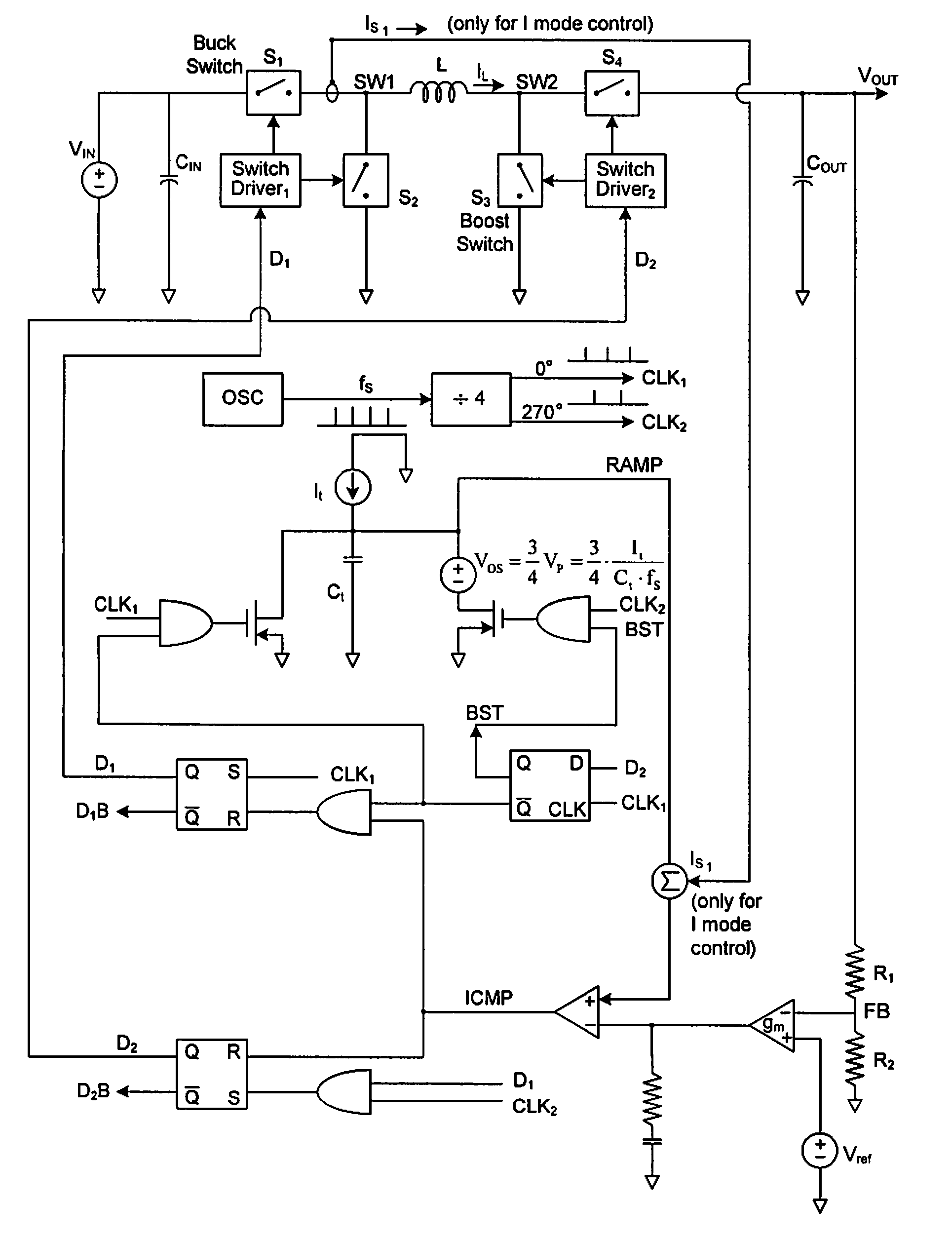
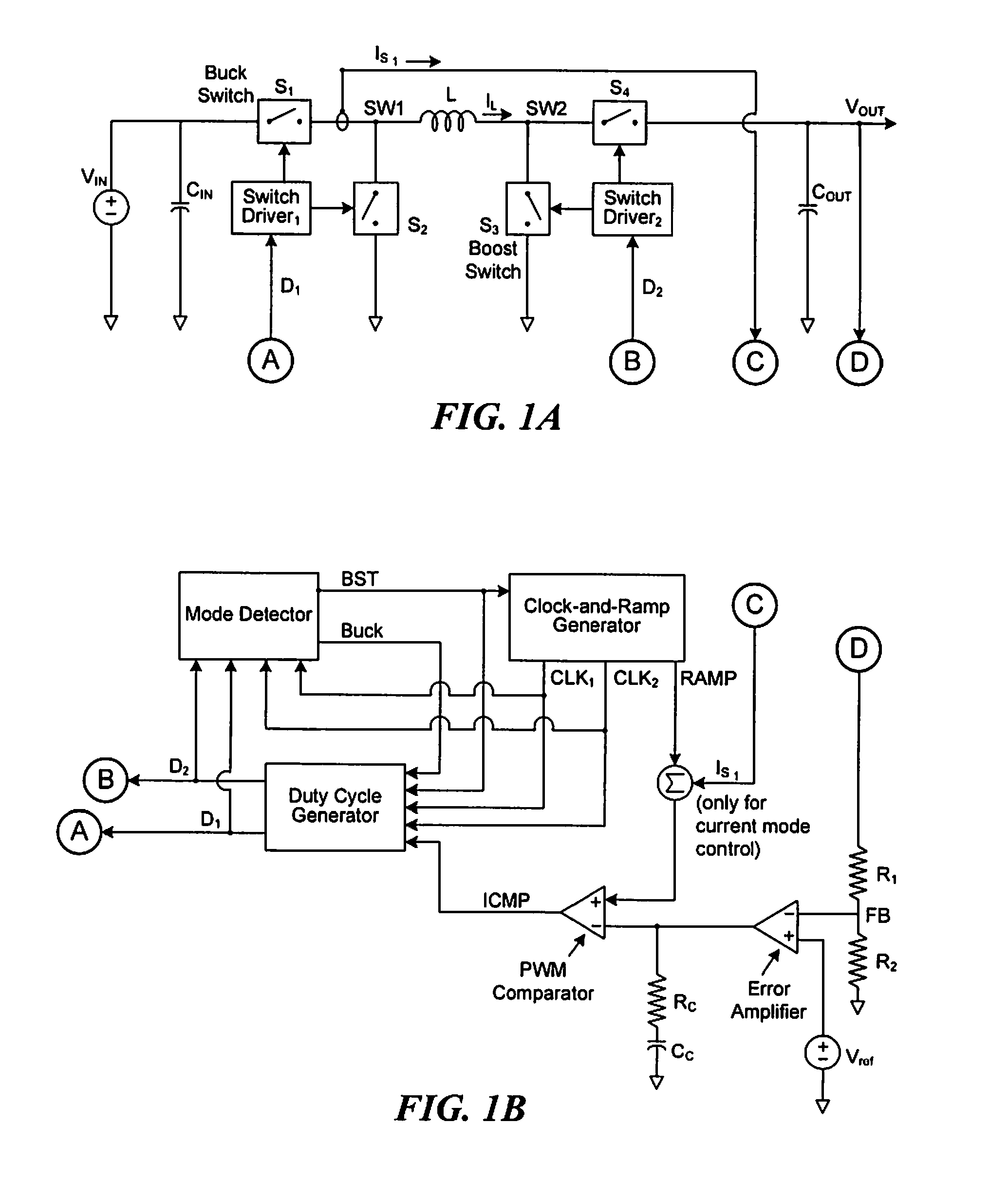
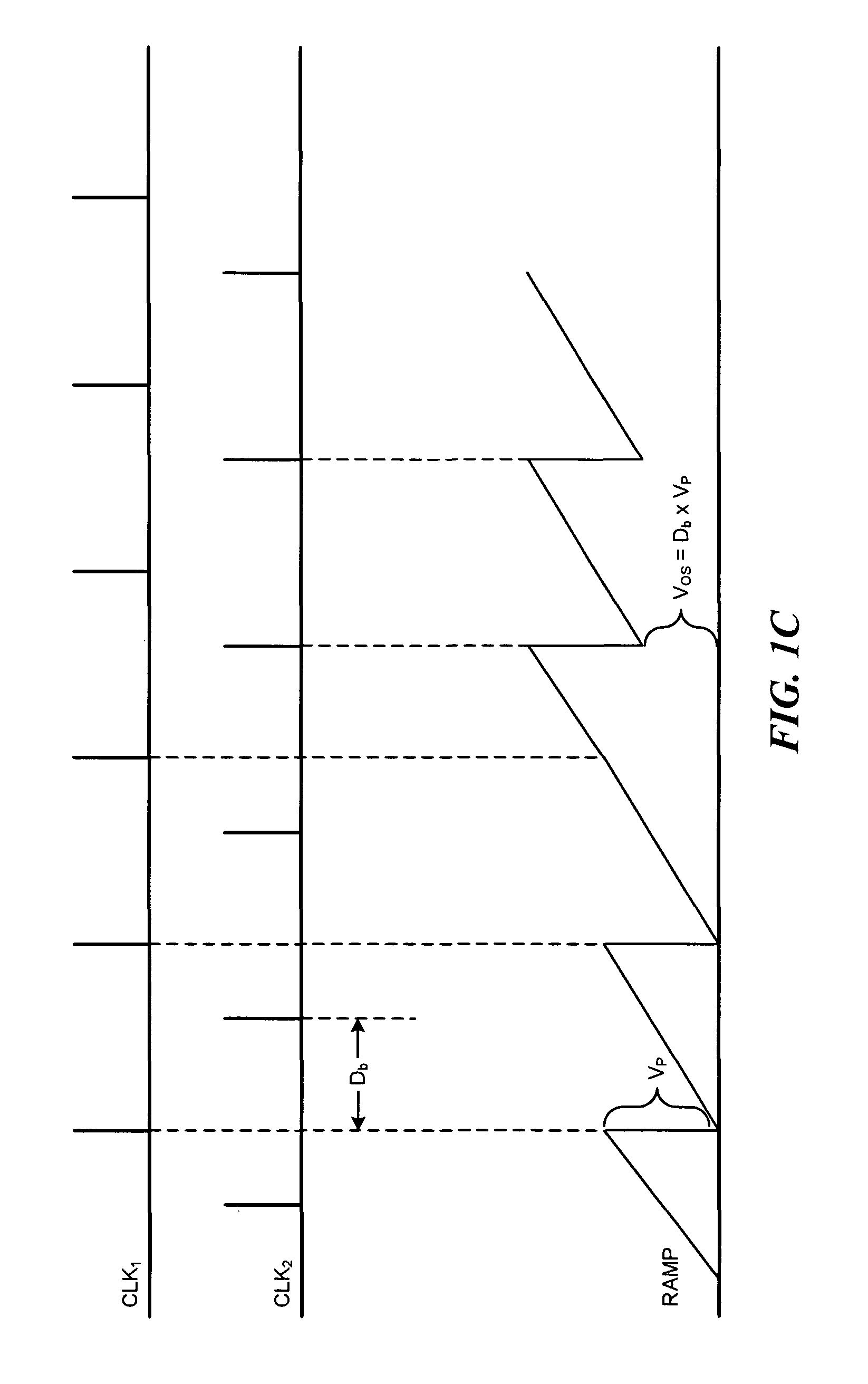
The following detailed description discloses methods and apparatus for efficient and automatic multimode SMPS's with input voltages that are above, below, or equal to the output voltages. FIG. 1 shows a schematic diagram of different parts of an automatic multimode converter. The power stage shown in FIG. 1A includes four switches that are all actively controlled. S1 is referred to as the buck switch, and S3 is referred to as the boost switch. The power stage converts an input voltage to a desired output voltage.

Problems solved by technology

On the other hand, a boost converter may only be used if the input voltage stays less than the output voltage at all times. The well-known buck-boost converter can operate automatically from input voltages above, below, or equal to the output voltage, but cannot maintain a high efficiency over a wide range of input voltages.
The buck-boost converter has a reasonable efficiency only when the input voltage is close to the output voltage, but it has much less efficiency than a buck converter when the input voltage is above the output voltage and much less than a boost converter when input voltage is below the output voltage.

Method used


Image

  • Switching regulator with automatic multi mode conversion
  • Switching regulator with automatic multi mode conversion
  • Switching regulator with automatic multi mode conversion

Examples


Embodiment Construction

Various embodiments of the invention will now be described. The following description provides specific details for a thorough understanding and enabling description of these embodiments. One skilled in the art will understand, however, that the invention may be practiced without many of these details. Additionally, some well-known structures or functions may not be shown or described in detail, so as to avoid unnecessarily obscuring the relevant description of the various embodiments.

The terminology used in the description presented below is intended to be interpreted in its broadest reasonable manner, even though it is being used in conjunction with a detailed description of certain specific embodiments of the invention. Certain terms may even be emphasized below; however, any terminology intended to be interpreted in any restricted manner will be overtly and specifically defined as such in this Detailed Description section.

The description of the embodiments of the invention and t...


PUM


Abstract

Methods and apparatus are disclosed for efficient switching regulators that adapt automatically to, and operate with, input voltages that are above, below, or equal to the output voltage. The disclosed switching regulators demonstrate advantages of both buck and boost converters at high efficiency.

Description

TECHNICAL FIELDThe embodiments described below relate, in general, to switch mode power supplies and, in particular, to efficient and automatic switching regulators operating from input voltages that are above, below, or equal to the output voltage.BACKGROUNDSwitch mode power supply (SMPS) is popular in powering ASICs, DRAMs, and other electronic devices because of its high efficiency. The selection of the SMPS topology requires consideration of the relationship of the input and output voltages. In some applications, the input voltage may be above, below, or equal to the output voltage.One example is the portable devices such as digital cameras that use a single-cell Li-lon battery to power a 3.3V rail, where the battery voltage is about 4.2V after charging up and drops to about 2.7V before the camera ceases to function. Appropriate efficiency is also required during the entire range of operation to maximize the battery usage life despite its limited size and weight. Such applicatio...

Claims


Application Information

Patent Timeline
IPC IPC(8): G05F1/618
CPCH02M3/1588Y02B70/16Y02B70/1466H02M2001/0032H02M3/1582Y02B70/10H02M1/0032
Inventor XU, PENG
Owner MONOLITHIC POWER SYST
Learn More