
Soldering apparatus

a technology of soldering apparatus and soldering head, which is applied in the direction of soldering apparatus, auxillary welding device, manufacturing tools, etc., can solve the problems of reducing the efficiency of soldering and inability to accommodate various electronic components of small siz

Inactive Publication Date: 2011-05-17
HON HAI PRECISION IND CO LTD
View PDF7 Cites 4 Cited by
  • Summary
  • Abstract
  • Description
  • Claims
  • Application Information

AI Technical Summary

Benefits of technology

The present patent is about a soldering apparatus with two movable soldering arms that can accommodate electronic components of varying sizes and can perform multiple joints simultaneously. The apparatus includes a base body, a pair of soldering arms, and an actuator to move the soldering arms. The soldering arms have a soldering tip with a positioning member and a heating member. The apparatus can be used with a manipulator to operate it. The technical effects of the patent are improved soldering efficiency, flexibility in accommodating various electronic components, and reduced soldering time.

Problems solved by technology

If the joints formed by soldering are unstable or the electronic components are misaligned, a soldering apparatus is required to be used to perform the resoldering process.
However, the soldering tip is usually in the form of a substantially cylindrical shape with a relatively large standard diameter, and thus cannot accommodate various electronic components of small size.
In addition, the soldering apparatus is provided typically with only one soldering tip and is also manually operated, such that if there is a need to redo multiple joints, the soldering efficiency is thereby reduced.

Method used


Image

  • Soldering apparatus
  • Soldering apparatus
  • Soldering apparatus

Examples


Embodiment Construction

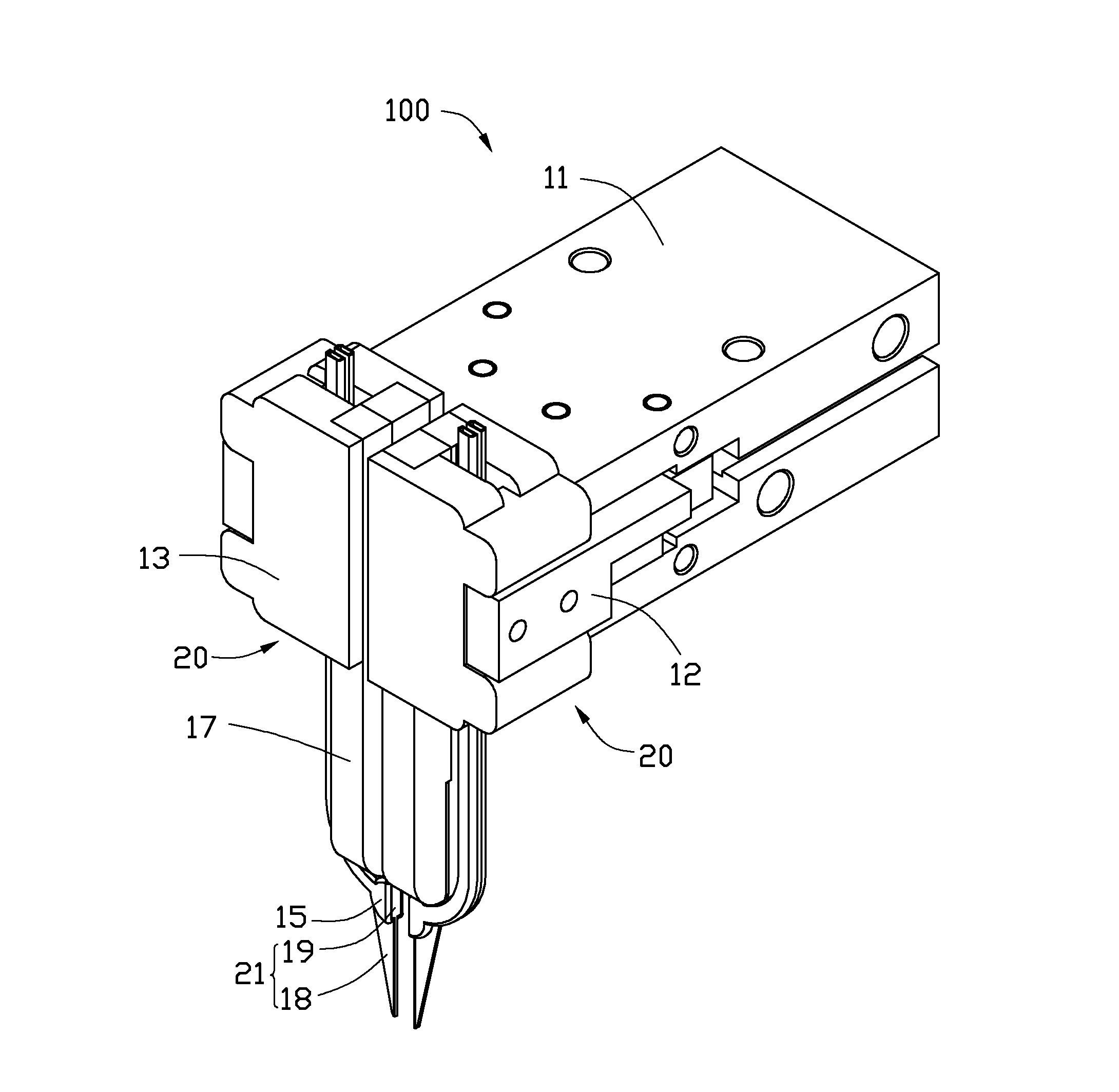
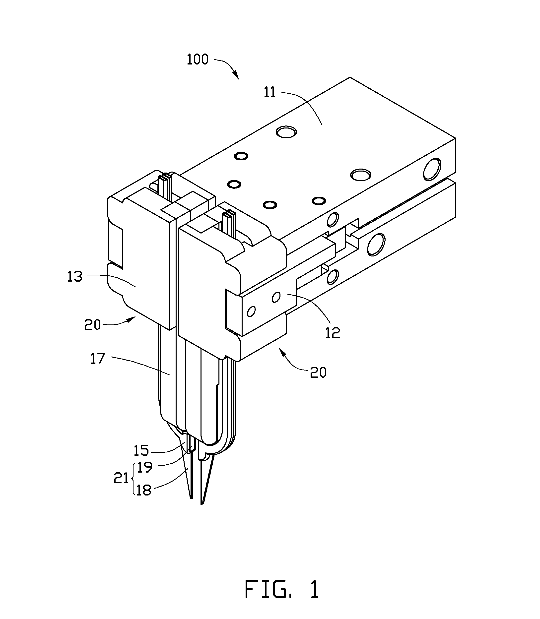
[0010]Referring to FIG. 1, one embodiment of a soldering apparatus 100 includes a base body 11, a pair of soldering arms 20 movable relative to each other, and an actuator 12 mounted to the base body 11 to move the soldering arms 20. The soldering apparatus 100 can be used to heat the solder for attaching a plurality of pins of electronic components to a printed circuit board. Because the soldering arms 20 are movable relative to each other, the distance between the pair of the soldering arms 20 is adjustable via the actuator 12, thus the soldering apparatus 100 can accommodate electronic components of varying sizes, and solder two joints simultaneously.

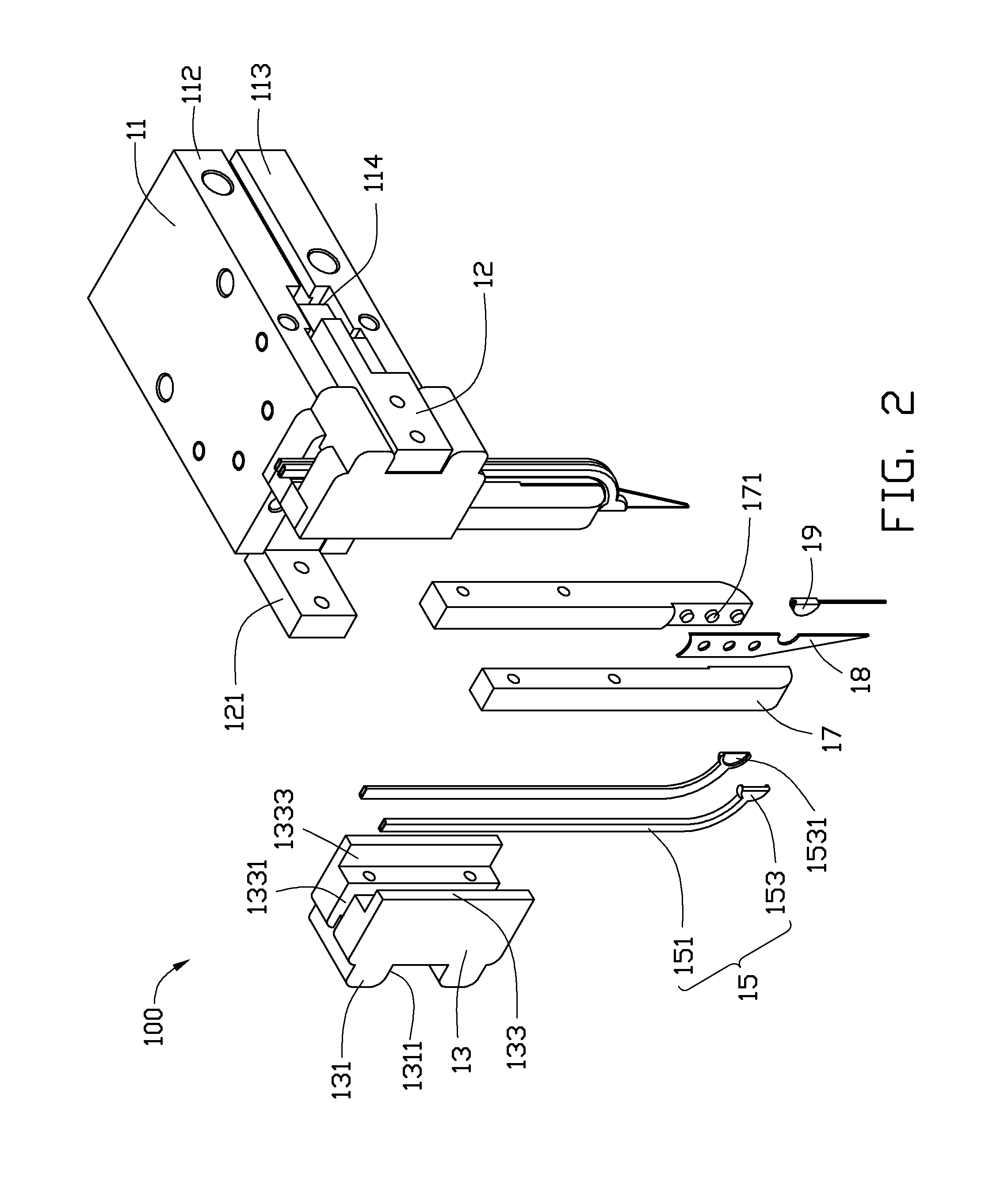
[0011]Referring to FIGS. 1 and 2, in this embodiment, each soldering arm 20 includes a fixing body 13, a pair of heating members 15 extending through the fixing body 13, a pair of clamping members 17 mounted to the fixing body 13, and a soldering head 21, including a positioning member 18 and a soldering tip 19 coupled to the positio...


PUM

PropertyMeasurementUnit
diameteraaaaaaaaaa
poweraaaaaaaaaa
sizeaaaaaaaaaa

Abstract

A soldering apparatus includes a base body, an actuator connected to the base body, and a pair of soldering arms connected to the actuator, each of the pair of soldering arms including a heating member and a soldering tip thermally coupled to the heating member. The pair of soldering arms is moveable and the actuator is controllable to move one soldering arm relative to the other soldering arm.

Description

BACKGROUND[0001]1. Technical Field[0002]The present disclosure generally relates to soldering, and particularly, to a soldering apparatus having at least two soldering arms.[0003]2. Description of Related Art[0004]An electronic device often houses a printed circuit board therein with a plurality of electronic components fixed thereon by soldering. If the joints formed by soldering are unstable or the electronic components are misaligned, a soldering apparatus is required to be used to perform the resoldering process. The typical soldering apparatus commonly includes a soldering tip to melt the solder tin for connecting a plurality of pins of the electronic components to the printed circuit board, and a heating member to heat the soldering tip. However, the soldering tip is usually in the form of a substantially cylindrical shape with a relatively large standard diameter, and thus cannot accommodate various electronic components of small size. In addition, the soldering apparatus is ...

Claims


Application Information

Patent Timeline
Patent Type & Authority Patents(United States)
IPC IPC(8): B23K37/00B23K37/04B23K3/02
CPCB23K1/0016B23K3/04B23K3/025B23K2201/42B23K2101/42
Inventor LI, SHEN-CHUNHSU, SHOU-KUOCHEN, YUNG-CHIEHLIANG, HSIEN-CHUAN
Owner HON HAI PRECISION IND CO LTD
Learn More