
Foot operated scupper plug

Inactive Publication Date: 2011-05-17
THE UNITED STATES OF AMERICA AS REPRESENTED BY THE SECRETARY OF THE NAVY
View PDF4 Cites 4 Cited by
  • Summary
  • Abstract
  • Description
  • Claims
  • Application Information

AI Technical Summary

Benefits of technology

[0008]The invention provides a new and improved method and apparatus for temporarily blocking a scupper opening on a ship through use of a scupper plug apparatus having an actuating arrangement which is capable of providing significantly more clamping force to a resilient body of the plug than was achievable in previously utilized approaches to temporarily blocking scupper openings. In some forms of the invention, the scupper plug apparatus is foot-operable, by a person standing next to the scupper, to thereby allow for application of substantially more force to an actuation lever of the scupper plug apparatus than is typically achievable through application of force by the hand or arm of a person installing a scupper plug. In some forms of the invention, the resilient body is composed of a closed-cell foam material which is more conformable to the shape of the scupper opening than the materials used in prior scupper plug approaches. In some forms of the invention, the resilient body is also molded to closely match the shape of a known scupper profile, when the resilient body is in a relaxed state, to thereby provide improved sealing between the resilient body and the scupper opening when the resilient body is compressed by an actuation apparatus in such a manner that an outer periphery of the resilient body expands into sealing contact with the scupper opening. Embodiments of the invention may also include a cam follower in the form of a rolling member to facilitate operation of an actuation arrangement used for compressing the resilient body.

Problems solved by technology

Experience has shown, however, that the rubber used in standard size and shaped rubber plugs is too hard to adequately seal to the irregular surfaces found on shipboard scuppers and drains.
This problem is exacerbated by the wing nuts not providing adequate leverage to sufficiently compress the rubber between the end plates.
Although this method achieves a complete seal of the scupper, it is a highly labor-intensive process to install and remove the wood blocks, and often results in damage to the paint or protective coatings on the scuppers and adjacent surfaces.
An additional disadvantage of the prior approaches to temporarily blocking scuppers, is that both previously-used approaches required a considerable amount of bending over or kneeling down on the steel deck of the ship to install and remove the plugs.

Method used


Image

  • Foot operated scupper plug
  • Foot operated scupper plug
  • Foot operated scupper plug

Examples


Embodiment Construction

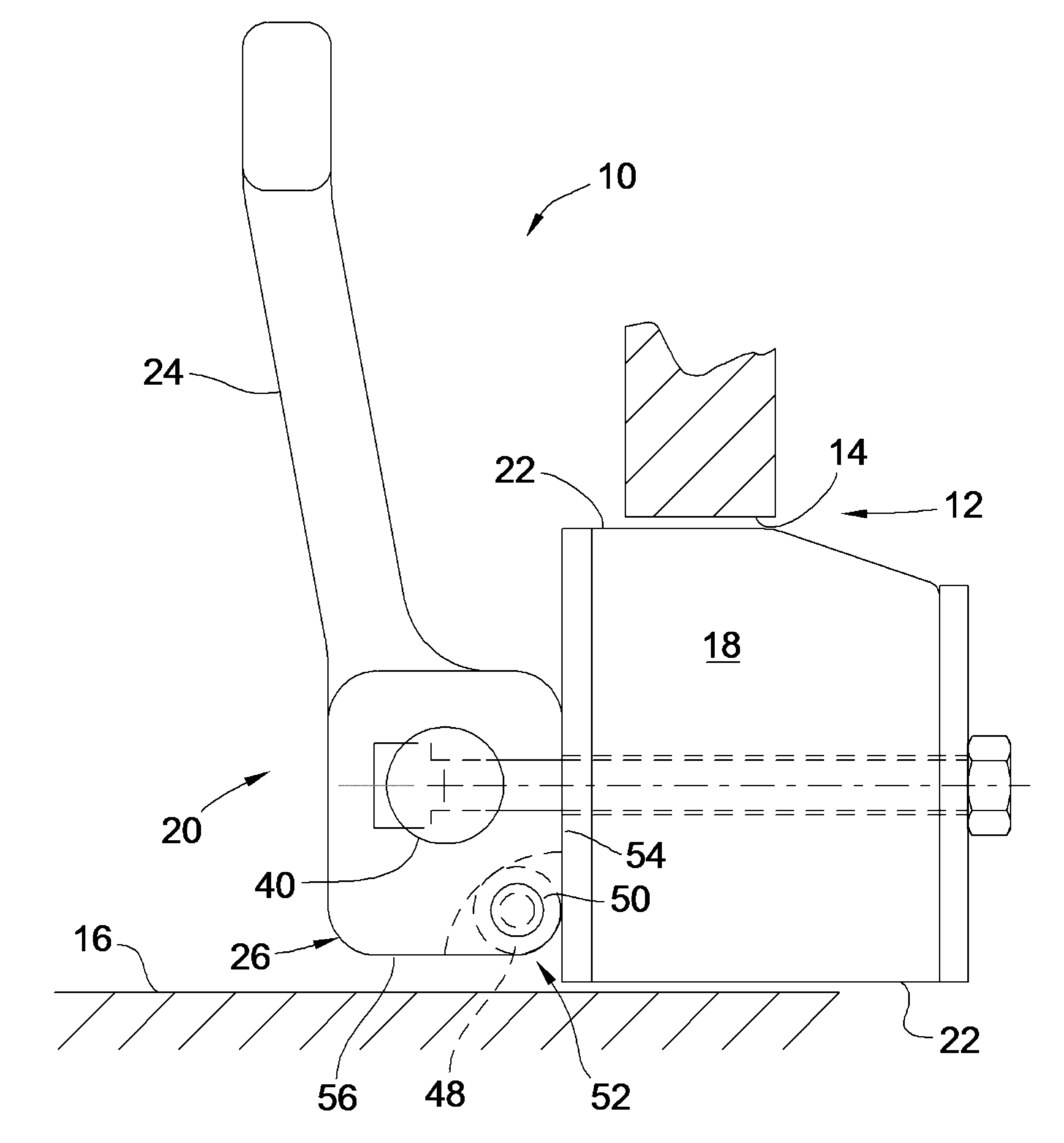
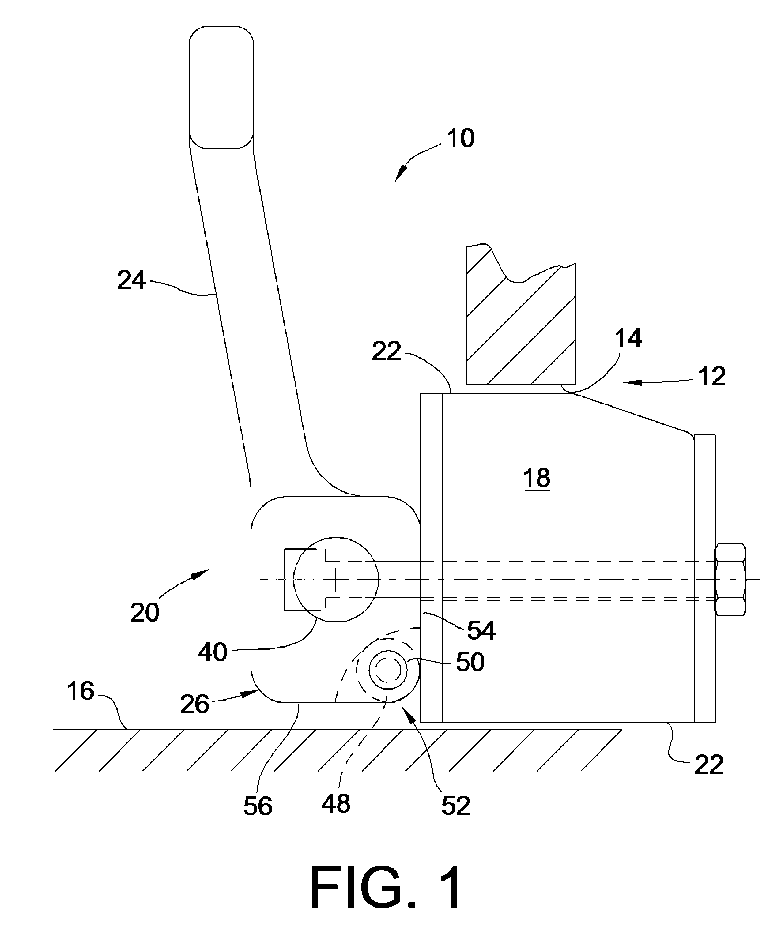
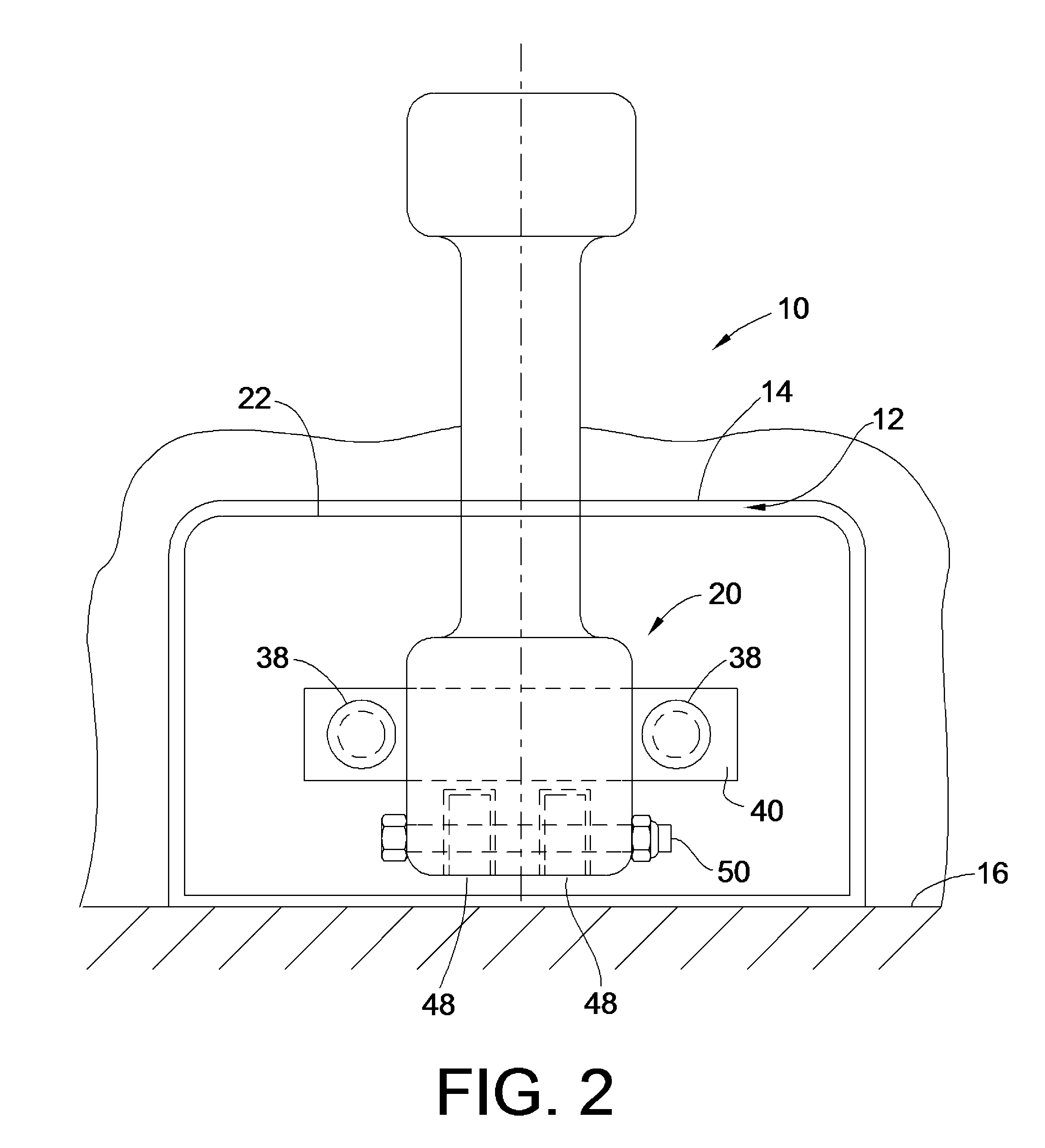
[0015]FIGS. 1 and 2 show a first exemplary embodiment of a foot-operable scupper plug 10, for blocking a scupper opening 12 on a ship, where the scupper has a scupper wall 14 defining a rectangular scupper shape, in combination with a deck 16 of the ship.

[0016]The first exemplary embodiment of the foot-operable scupper plug 10 includes a resilient body 18 and a foot-operable actuating arrangement 20.

[0017]The resilient body 18 has a periphery 22 thereof, which substantially matches the scupper shape, and is adapted for insertion into the scupper opening 12, when the resilient body 18 is in a relaxed state thereof, as shown in FIGS. 1 and 3.

[0018]The foot-operable actuating arrangement 20 is operatively mounted on and connected to the resilient body 18, in a manner described in more detail below, for compressing the resilient body 18 in a manner urging at least a portion of the outer periphery 22 of the resilient body 18 to expand outward in an expanded state, as shown in FIG. 4. As ...


PUM


Abstract

A scupper plug apparatus is foot-operable, by a person standing next to the scupper, to apply substantially more force for sealing the scupper than is typically achievable through application of force by the hand or arm of a person installing a scupper plug. A resilient body of the scupper plug formed from highly conformable closed-cell foam to closely match the shape of the scupper. A rolling member is used as a cam follower in an actuation arrangement for compressing the resilient body.

Description

FEDERALLY-SPONSORED RESEARCH AND DEVELOPMENT[0001]This invention (Navy Case No. 97,901) is assigned to the United States Government and is available for licensing for commercial purposes. Licensing and technical inquires may be directed to the Office of Research and Technical Applications, Space and Naval Warfare Systems Center, San Diego, Code 2112, San Diego, Calif. 92152; voice (619) 553-2778; email T2@spawar.navy.mil.BACKGROUND OF THE INVENTION[0002]Large ships, such as military fleet oilers, often have vertical coamings or bulwarks extending upward from the intersection of the deck and the hull of the ship, which in some cases extend upward from the deck to waist-height of a person standing on the deck. Such coamings and bulwarks typically include a plurality of openings, known as deck drains or “scuppers” at deck level, to permit controlled drainage overboard of water landing on the deck from waves while the ship is at sea, or from rainfall while the ship is at sea or in port....

Claims


Application Information

Patent Timeline
IPC IPC(8): B63B13/00
CPCB63B13/02B63B19/08B63B17/00
Inventor DOLTON, JOHN A
Owner THE UNITED STATES OF AMERICA AS REPRESENTED BY THE SECRETARY OF THE NAVY
Learn More