
Annuloplasty ring for ischemic mitral valve insuffuciency

a technology of mitral valve and annuloplasty ring, which is applied in the field of medical devices, can solve the problems of poor reliability and durability of the operation to correct ischemic mitral valve insufficiency, mitral regurgitation, and inability to fully discharge, and achieve the effect of reducing excessively the overall orifice area

Inactive Publication Date: 2011-05-03
EDWARDS LIFESCIENCES CORP
View PDF58 Cites 50 Cited by
  • Summary
  • Abstract
  • Description
  • Claims
  • Application Information

AI Technical Summary

Benefits of technology

The present invention provides an improved annuloplasty ring for repairing a mitral valve annulus that can better address the needs of patients with certain pathological conditions. The ring has a ratio between the distance between the anterior and posterior half-rings that is lower than 3:4. The invention also includes a method for implanting the annuloplasty ring and a specific design for correcting ischemic mitral valve insufficiency. The technical effects of the invention include improved mitral valve operation, reduced leaflet abnormalities, and reduced risk of complications during surgery.

Problems solved by technology

In severe cases of left ventricle dilatation, the tethering of the chordae prevents the leaflets from coapting resulting in mitral regurgitation.
The resulting increased tension in the chordae reduces the ability of the leaflets to come together during systole, which can lead to mitral valve insufficiency.
Although good results have been reported with the downsizing technique, the reliability and durability of this operation to correct ischemic mitral valve insufficiency are not as good as for other causes of mitral valve insufficiency using the same techniques.
This is largely due to the fact that a remodeling annuloplasty with currently available rings corrects only one anomaly, and various other functional anomalies seen in ischemic mitral valve insufficiency may not be corrected as effectively.
Such rings would not be suitable for correcting a mitral valve deficiency.

Method used


Image

  • Annuloplasty ring for ischemic mitral valve insuffuciency
  • Annuloplasty ring for ischemic mitral valve insuffuciency
  • Annuloplasty ring for ischemic mitral valve insuffuciency

Examples


first embodiment

[0057]In FIG. 5 an annular prosthesis for mitral valve according to the present invention is shown. It substantially has the same shape as the one rendered in FIG. 4 but the ratio between the height and the width of the prosthesis is lower than 3:4, for instance equal to 2.5:4 or equal to 2:4.

[0058]For every size of prosthesis two or more reduced ratios can therefore be provided. By “size” the dimension of the transverse width of the prosthesis is meant; the “size” represents the clinical parameter on the basis of which the prosthesis is selected in each single clinical case in examination, and it is also the identifying parameter for the prosthesis.

[0059]The lower ratio as compared with the prostheses currently used for annuloplastic surgery allows its use in selected cases of pathologies that are not treatable in adequate way with conventional prostheses.

[0060]The lower ratios in this case have the function to treat pathologies characterised by reduced movement of the leaflets wit...

second embodiment

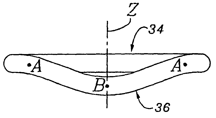
[0061]In FIG. 6 an annular prosthesis for mitral valve according to the present invention is shown. In this case the natural ratio height / width of 3:4 is maintained in order to define the curving radii of the two lateral parts of the anterior half-ring. In the central zone, in proximity of the point 7, the distance between the posterior half-ring 1 and the front half-ring 2 is reduced, with the aim of obtaining a height / width ratio lower than 3:4. The central zone of the posterior half-ring 2 therefore takes a configuration that recalls the dog bone or gull wing shape and increases the coaptation at central level by limiting the annular reduction at level of the commissure.

[0062]In some extreme cases, it could be useful to make the distance between the two half-rings in the central zone equal to zero, in order to obtain an eight-shape configuration, in order to improve the coaptation at central level. This remodeling simulates the double orifice operation, in which the leaflets are ...

third embodiment

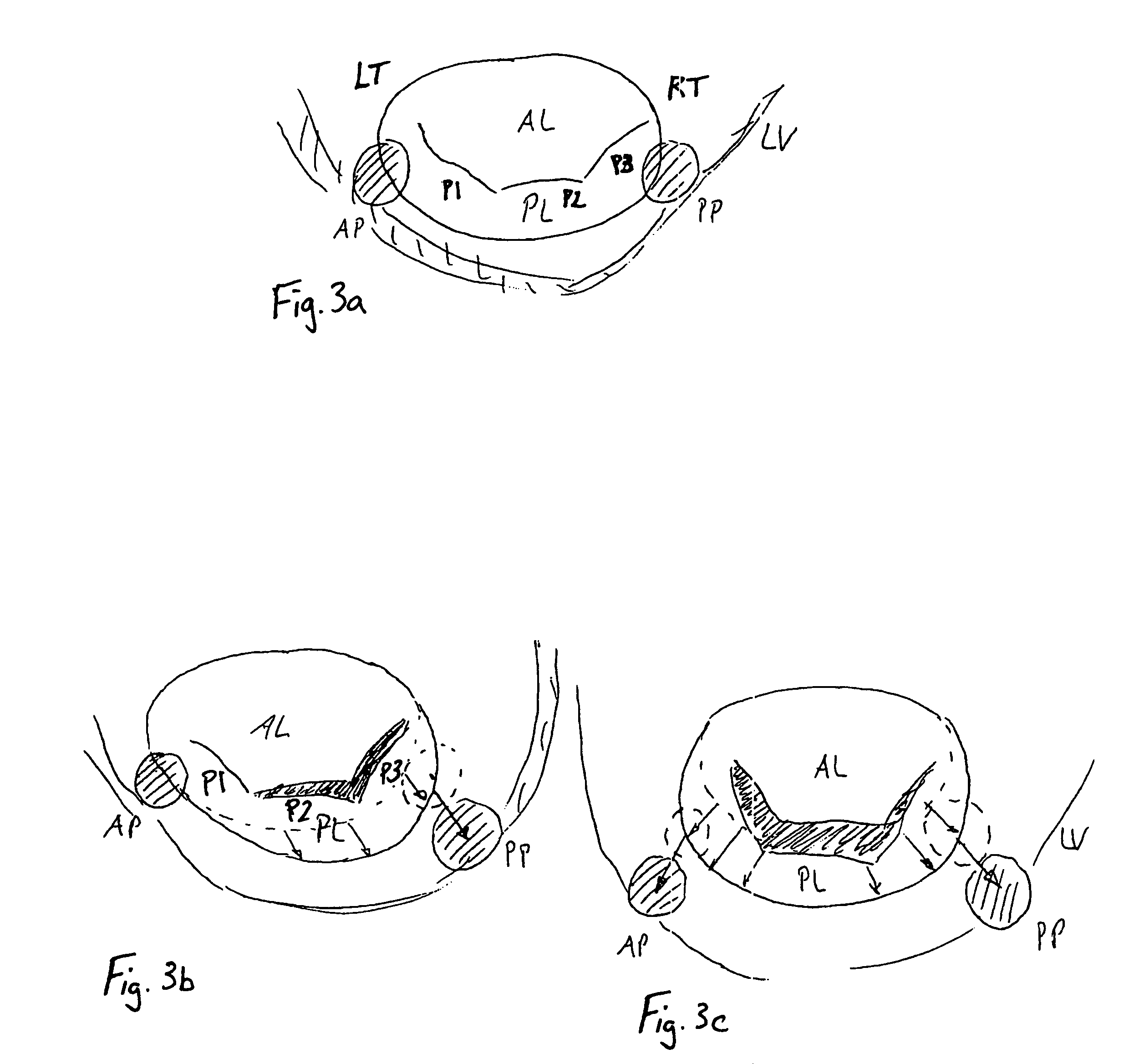
[0063]In FIG. 7 an annular prosthesis for mitral valve according to the present invention is shown. In this embodiment the curving radius of one of the lateral zones, for instance the second lateral zone (right) 10, is increased so as to induce a selective increase of the competence in correspondence of the valve sector with reduced mobility of the leaflets (bad asymmetric apposition of the leaflets as in ischaemic pathology). It is thus obtained that one part of the prosthesis, for instance the first lateral zone (left) 9, maintains a configuration substantially similar to the traditional prosthesis and one part, for instance the second lateral zone (right) 10, gets a sized configuration. In other words the distance between the middle point of the first lateral zone (left) 9 and the longitudinal plane 4 is greater than the distance between the middle point of the second lateral zone (right) 10 and the longitudinal plane.

[0064]The prosthesis, according to the present invention, can ...


PUM


Abstract

A remodeling mitral annuloplasty ring with a reduced anterior-to-posterior dimension to restore coaptation between the mitral leaflets in mitral valve insufficiency (IMVI). The ring has a generally oval shaped body with a major axis perpendicular to a minor axis, both perpendicular to a blood flow axis. An anterior section lies between anteriolateral and posteriomedial trigones, while a posterior section defines the remaining ring body and is divided into P1, P2, and P3 segments corresponding to the three scallops of the same nomenclature in the posterior leaflet of the mitral valve. The anterior-to-posterior dimension of the ring body is reduced from conventional rings; such as by providing, in atrial plan view, a pulled-in P3 segment. Viewed another way, the convexity of the P3 segment is less pronounced than the convexity of the P1 segment. In addition, the ring body may have a downwardly deflected portion in the posterior section, preferably within the P2 and P3 segments. The downwardly deflected portion may have an apex which is the lowest elevation of the ring body and may be offset with respect to the center of the downwardly deflected portion toward the P1 segment. A sewing cuff may have an enlarged radial dimension of between 5-10 cm, or only a portion of the sewing cuff may be enlarged.

Description

RELATED APPLICATIONS[0001]The present application is a continuation of U.S. application Ser. No. 10 / 678,338, filed Oct. 3, 2003, now abandoned which is a continuation-in-part to U.S. application Ser. No. 10 / 192,516, filed Jul. 8, 2002, now U.S. Pat. No. 6,858,039 entitled “Mitral Valve Annuloplasty Ring Having a Posterior Bow.” The present application is also a continuation-in-part to U.S. application Ser. No. 10 / 144,932, filed May 15, 2002, now U.S. Pat. No. 6,726,717 entitled “Annular Prosthesis for Mitral Valve,” which claims priority under 35 U.S.C. §119 to Italian Application No. MI 2001A 001012, filed May 17, 2001.FIELD OF THE INVENTION[0002]The present invention relates generally to medical devices, specifically to an annuloplasty ring and related procedure for surgically reconstructing the mitral valve annulus of a patient's heart. More specifically, this invention relates to a mitral valve annuloplasty ring and corresponding technique designed to correct an abnormal annulus...

Claims


Application Information

Patent Timeline
Patent Type & Authority Patents(United States)
IPC IPC(8): A61F2/24
CPCA61F2/2448A61F2/2409A61F2/246
Inventor ALFIERI, OTTAVIOCARPENTIER, ALAIN F.MAISANO, FRANCESCOMCCARTHY, PATRICKREDAELLI, ALBERTO
Owner EDWARDS LIFESCIENCES CORP
Learn More