
Tape measure endpiece

a technology of endpieces and tapes, which is applied in the field of endpieces, can solve the problems of complicated and time-consuming, difficult to lay the measuring blade b>101/b> flat on the surface to be measured, and more difficult to measur

Inactive Publication Date: 2011-04-05
POLKHOVSKIY NIKOLAY
View PDF29 Cites 37 Cited by
  • Summary
  • Abstract
  • Description
  • Claims
  • Application Information

AI Technical Summary

Benefits of technology

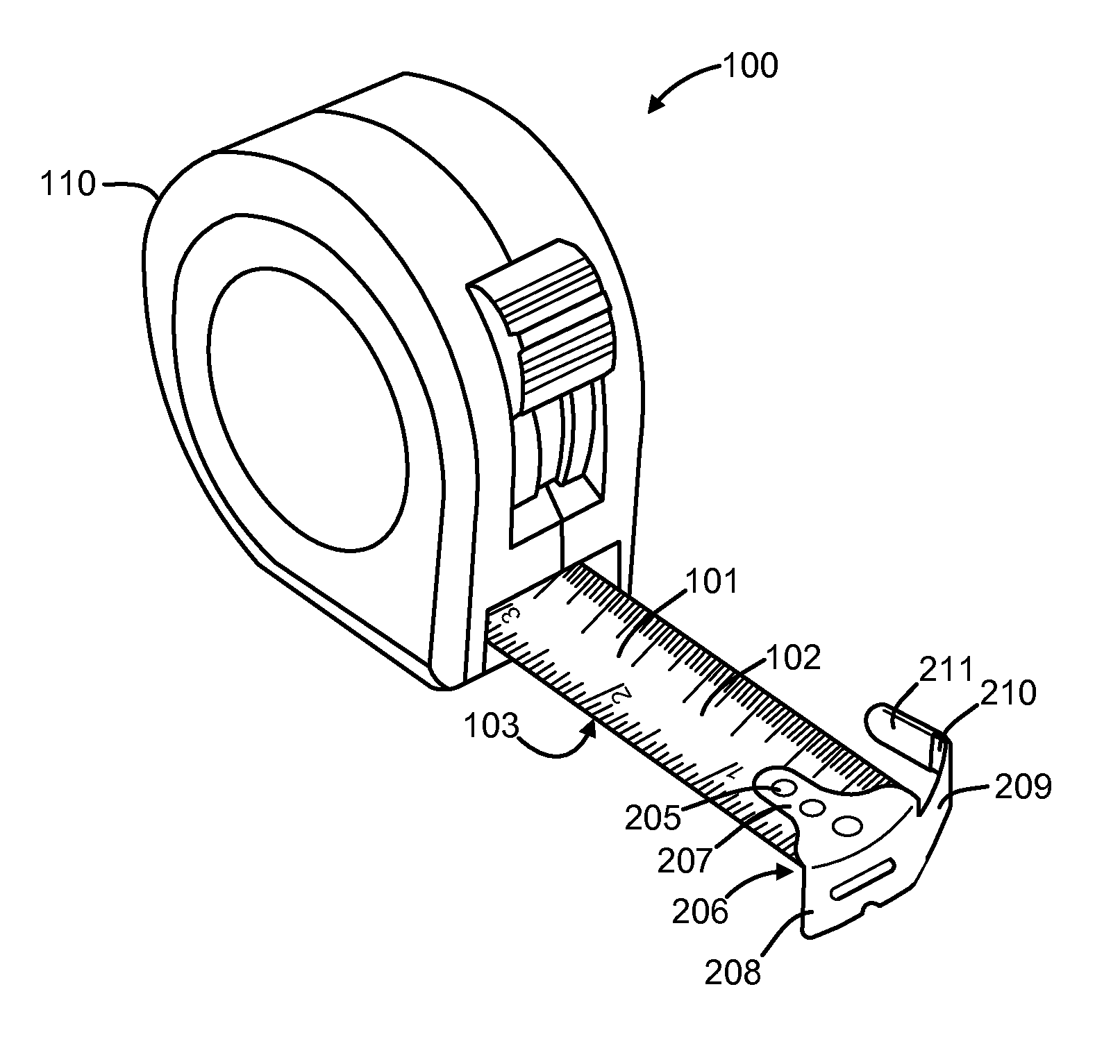
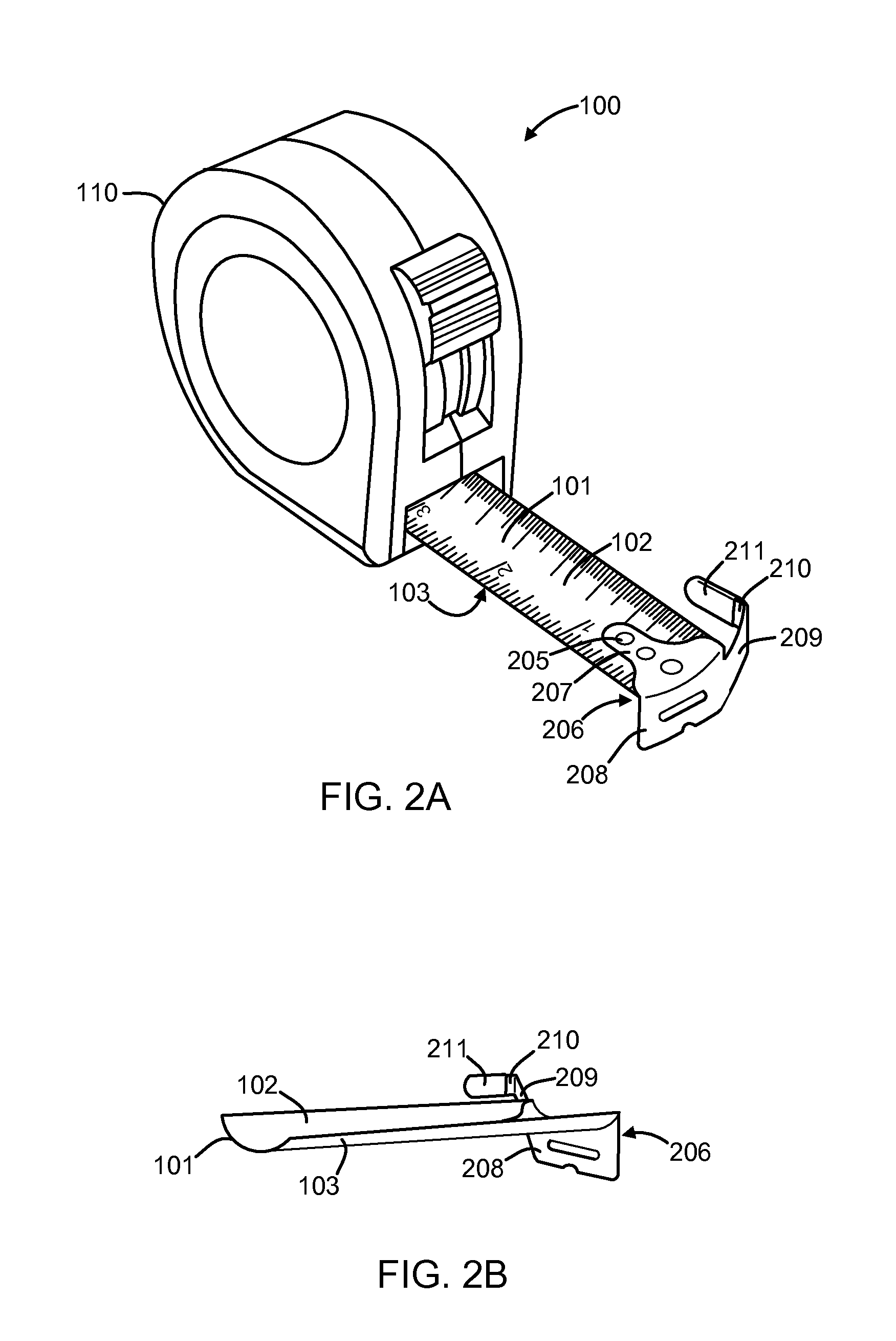
[0008]A tape measure endpiece is disclosed that can hook the measuring blade onto the edge of an object to be measured. The hooking member of the endpiece is positioned to avoid impacting the performance of the measuring blade when not using the hooking member to make measurements (e.g., when making different types of measurements and when stored). In one embodiment, the endpiece comprises a tab extending below the plane of the measuring blade, an arm extending from the tab beyond the edge of the measuring blade, and a hooking member extending from the end of the arm. In other embodiments, the endpiece further comprises a support that extends above the plane of the measuring blade, with the arm extending from the support and supporting the hooking member. In some embodiments, the arm and hooking member are moveable to allow greater flexibility in making measurements.

Problems solved by technology

This problem is especially prevalent when the measuring blade 101 is extended a long distance from the housing 110 of the tape measure 100 to make a measurement.
A hooking member that extended directly above the top surface of the measuring blade 101 would also make measurements more difficult since it would be necessary, for some measurements, to turn the housing 110 over or upside down in order to hook onto the object to be measured, making it difficult to then lay the measuring blade 101 flat on the surface to be measured.
This requirement for using different endpieces 106 for different measurements, however, can be complicated and time consuming when several different measurements need to be performed on a regular basis.

Method used


Image

  • Tape measure endpiece
  • Tape measure endpiece
  • Tape measure endpiece

Examples


Embodiment Construction

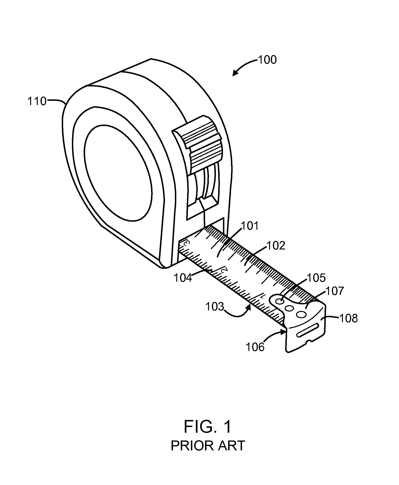
[0020]FIG. 1 is perspective view of a tape measure 100 with a conventional endpiece 106 attached to the free end of a measuring blade 101. The top surface 102 of the measuring blade 101 can include imprinted markings 104 (e.g., lines and numbers) corresponding to units of measure (e.g., inches, centimeters, etc.). As shown in FIG. 1, the conventional endpiece 106 has a mount 107 that extends along the top surface 102 of the measuring blade 101 and attaches the conventional endpiece 106 to the measuring blade 101 by rivets or other fasteners that pass from the top surface 102 to the bottom surface 103 of the measuring blade 101 through holes 105 in the mount 107 and in the measuring blade 101.

[0021]The conventional endpiece 106 also has a tab 108 that extends downward from the mount 107 substantially perpendicular to the end of the measuring blade 101. The tab 108 can be substantially the same width as the width of the measuring blade 101. It will be understood that there are several...


PUM


Abstract

A tape measure endpiece is disclosed that can hook the measuring blade onto the edge of an object to be measured. The hooking member of the endpiece is positioned to avoid impacting the performance of the measuring blade when not using the hooking member to make measurements (e.g., when making different types of measurements and when stored). In one embodiment, the endpiece comprises a tab extending below the plane of the measuring blade, an arm extending from the tab beyond the edge of the measuring blade, and a hooking member extending from the end of the arm. In other embodiments, the endpiece further comprises a support that extends above the plane of the measuring blade, with the arm extending from the support and supporting the hooking member. In some embodiments, the arm and hooking member are moveable to allow greater flexibility in making measurements.

Description

FIELD OF THE INVENTION[0001]The subject matter disclosed herein relates to endpieces for securing the free end of a measuring blade of a tape measure to an object.BACKGROUND OF THE INVENTION[0002]A tape measure 100 as shown in FIG. 1 is a well known device used to take measurements of an object (e.g., the length of an object). A tape measure 100 includes a housing 110 that contains a coiled length of a measuring blade 101 that extends from the housing 110 while taking measurements and retracts back into the housing 110 for storage after the measurement has been taken.[0003]Since the distance to be measured by the tape measure 100 often exceeds the reach of the user and the user typically can only devote one hand to making the measurement (e.g., the other hand is holding a tool or writing device), the measuring blade 101 can be designed with a concave surface to allow the measuring blade 101 to remain rigid when it is extended over a large distance. The measuring blade can also be de...

Claims


Application Information

Patent Timeline
Patent Type & Authority Patents(United States)
IPC IPC(8): G01B3/10
CPCG01B3/1056
Inventor POLKHOVSKIY, NIKOLAY
Owner POLKHOVSKIY NIKOLAY
Learn More