Imaging lens and imaging apparatus using imaging lens

a technology which is applied in the field of imaging lens and imaging apparatus using imaging lens, can solve the problems of reducing resolution, deteriorating optical performance of imaging lens, and achieves the effects of lowering the optical performance of imaging lens, high environmental resistance, and high environmental resistan

Inactive Publication Date: 2011-03-08
FUJI PHOTO OPTICAL CO LTD
View PDF10 Cites 16 Cited by
  • Summary
  • Abstract
  • Description
  • Claims
  • Application Information

AI Technical Summary

Benefits of technology

[0011]The invention has been made in order to solve the above-mentioned problems, and an object of the invention is to provide an imaging lens having a small size, a long back focal length, and high environmental resistance and an imaging apparatus using the imaging lens.
[0027]According to the imaging lens and the imaging apparatus using the imaging lens of the above-mentioned aspects, the imaging lens includes, in order from the object side, the first lens group having the positive power, the stop, and the second lens group having the positive or negative power. The first lens group includes, in order from the object side, the first lens, which is the biconcave lens, the second lens that has the positive power and includes the convex image-side surface, and the third lens that has the positive power and includes the convex object-side surface. The second lens group includes, in order from the object side, the fourth lens that has the negative power and includes the concave image-side surface, and the fifth lens, which is the biconvex lens. Each of the first to fifth lenses is a single spherical glass lens. With this structure, it is possible to obtain an imaging lens having a small size, a long back focal length and high environmental resistance.
[0028]That is, both the lens closest to the object side in the first lens group and the lens closest to the object side in the second lens group have negative powers. Particularly, the lens closest to the object side in the first lens group is the biconcave lens. Therefore, it is possible to increase the back focal length while reducing the length of the entire imaging lens system.
[0030]The cement of the cemented lens or the plastic lens is made of a material, such as a polymer material, having a melting point lower than that of a glass material. The low-melting-point material is more likely to be deformed by the influence of the temperature or humidity than the glass material, and the optical characteristics thereof, such as the refractive index, are also more likely to be changed. In addition, the low-melting-point material is more likely to be transformed than the glass material. Therefore, when the imaging lens is used for a long time, the optical performance of the imaging lens is lowered.
[0031]According to the above-mentioned aspects of the invention, the imaging lens is not made of the low-melting-point material, but is made of only the glass member having high environmental resistance. Therefore, it is possible to obtain an imaging lens and an imaging apparatus having high environmental resistance. In addition, since the imaging lens includes only the spherical lenses, it is possible to easily manufacture the imaging lens, as compared to an imaging lens including aspheric lenses. As a result, it is possible to reduce apparatus costs.
[0032]When the environmental resistance of the imaging lens is increased, the deterioration of the optical performance of the imaging lens caused by the influence of an environment is reduced. For example, when the environmental resistance of the imaging lens is high, the transformation or deformation of the lens member is reduced, and the deterioration of the optical performance of the imaging lens is reduced even when the imaging lens is used for a long time or it is provided in a low-temperature environment or a high-temperature and high-humidity environment in a short period of time. In addition, when the environmental resistance of the imaging lens is high, the deterioration of the optical performance of the imaging lens is reduced even when the temperature of the imaging lens varies greatly from a room temperature during image capture in a cold region or a tropical region.

Problems solved by technology

Therefore, a cement of the cemented lens or a plastic lens forming the imaging lens is likely to be transformed or deformed, which may cause deterioration of the optical performance of the imaging lens, for example, a reduction in resolution.
Therefore, it is necessary to prevent the optical performance of the imaging lens from being lowered due to the transformation or deformation of each lens, or the variation in the refractive index of each lens when the imaging lens is provided in a severe environment.
The problem of the deterioration of the optical performance of the imaging lens is not limited to the in-vehicle imaging lens, but it also arises in an imaging lens including a plastic lens or a cemented lens.

Method used


Image

  • Imaging lens and imaging apparatus using imaging lens
  • Imaging lens and imaging apparatus using imaging lens
  • Imaging lens and imaging apparatus using imaging lens

Examples


Embodiment Construction

[0049]Hereinafter, an imaging lens and an imaging apparatus using the imaging lens according to exemplary embodiments of the invention will be described in detail with reference to the accompanying drawings.

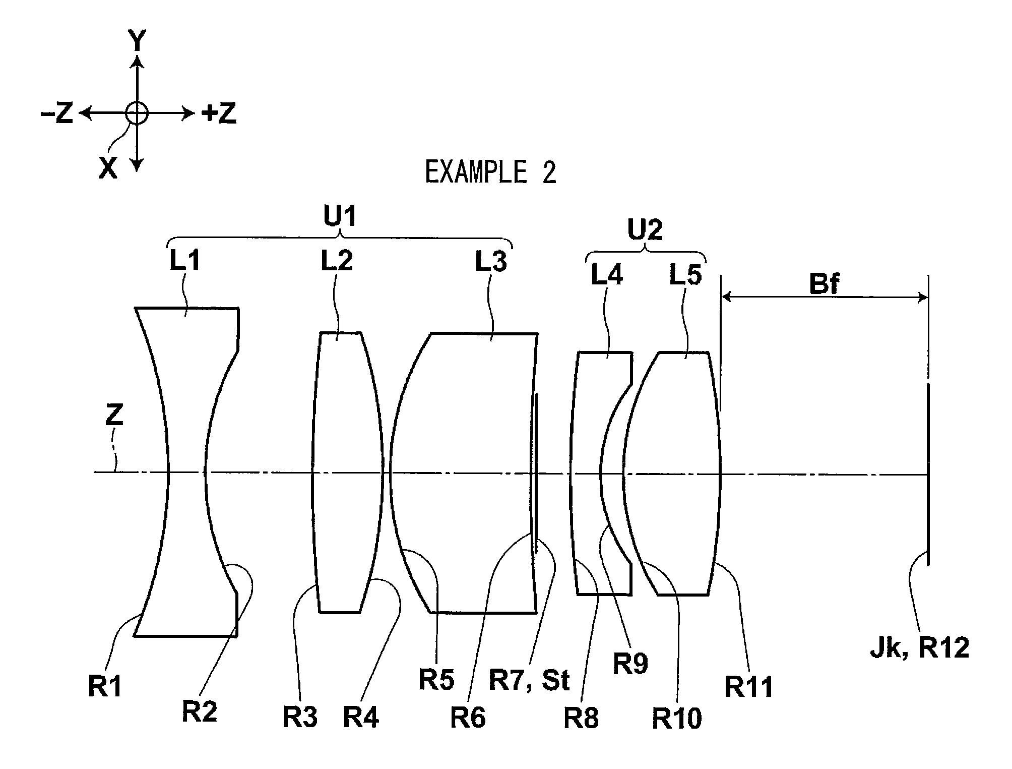
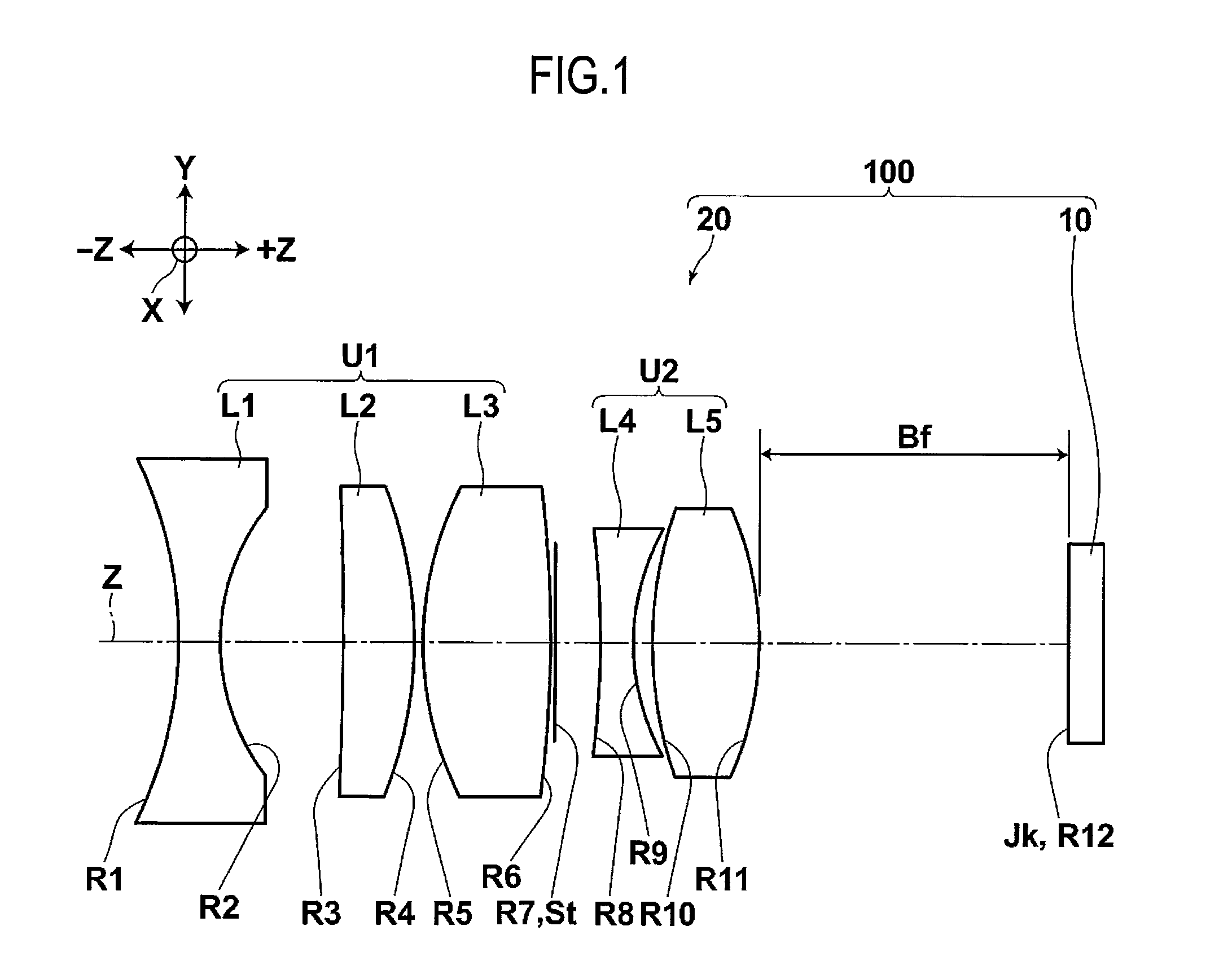
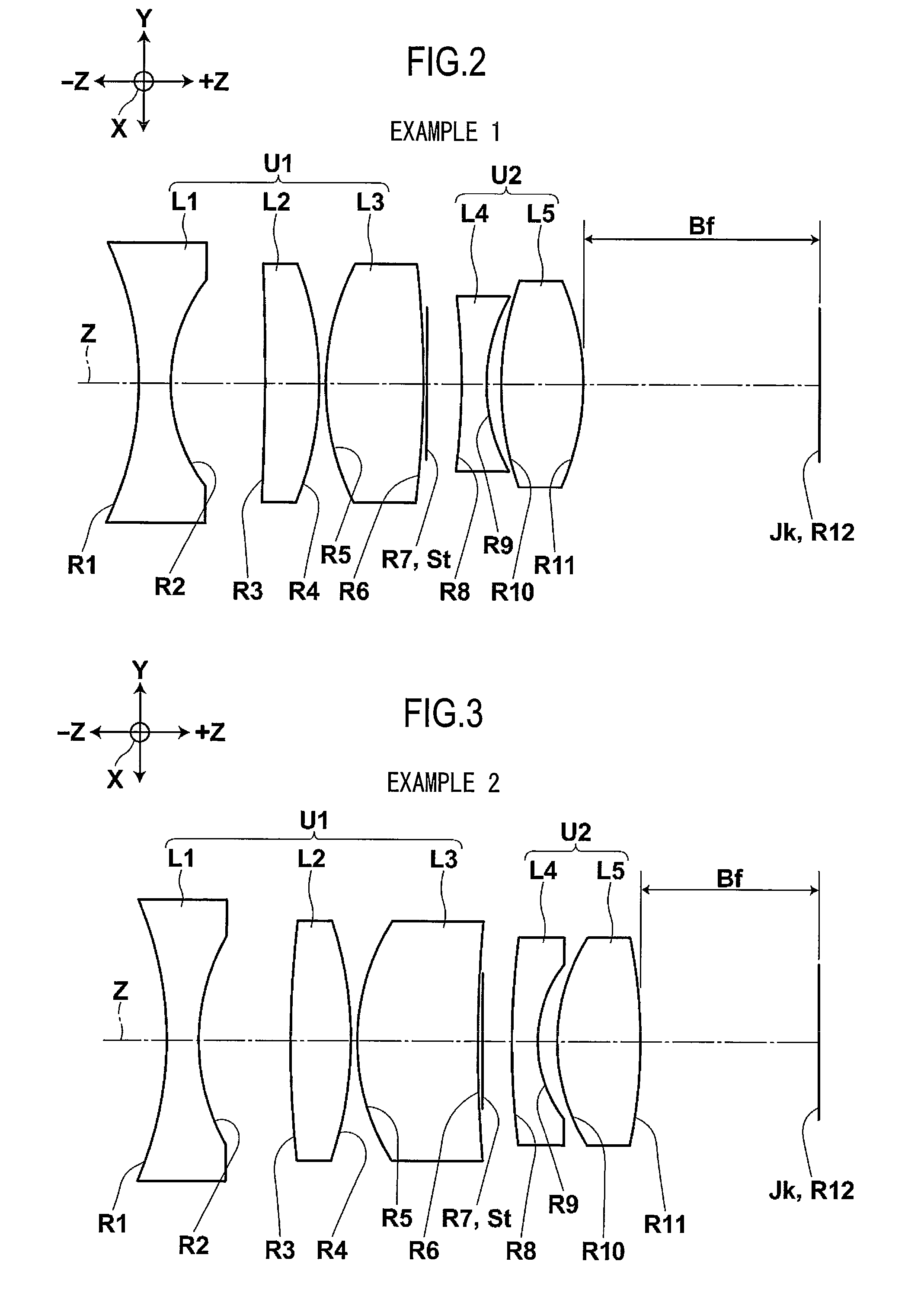
[0050]FIG. 1 is a cross-sectional view schematically illustrating the structure of an imaging apparatus using an imaging lens according to an embodiment of the invention.

[0051]An imaging lens 20 shown in FIG. 1 is mainly used for an in-vehicle imaging apparatus that captures a situation on the front side of a vehicle, and focuses the image of an object on a light receiving surface Jk of an imaging device 10, such as a CCD or a CMOS. The imaging device 10 converts an optical image formed by the imaging lens 20 into an electric signal to obtain an image signal indicating the optical image.

[0052]The imaging lens 20 has an F number of 2.0 to 4.0 and a total angle of view of about 40° to 60°. The imaging lens 20 has a small size and a long back focal length and effectively corrects al...


PUM


Abstract

An imaging lens includes, in order from an object side, a first lens group having a positive power, an aperture diaphragm, and a second lens group having a positive or negative power. The first lens group includes, in order from the object side, a first lens which is a biconcave lens, a second lens that has a positive power and includes a convex image-side surface, and a third lens that has a positive power and includes a convex object-side surface. The second lens group includes, in order from the object side, a fourth lens that has a negative power and includes a concave image-side surface, and a fifth lens which is a biconvex lens. Each of the first to fifth lenses is a single spherical glass lens.

Description

CROSS-REFERENCE TO RELATED APPLICATIONS[0001]This application is based upon and claims the benefit of priority from the Japanese Patent Application No. 2008-276247 filed on Oct. 28, 2008; the entire contents of which are incorporated herein by reference.BACKGROUND OF THE INVENTION[0002]1. Field of the Invention[0003]The present invention relates to an imaging lens that captures the image of an object and an imaging apparatus using the imaging lens.[0004]2. Description of the Related Art[0005]An in-vehicle imaging apparatus has been proposed which monitors the front of a vehicle. The imaging apparatus is provided in the vehicle to monitor the deviation of the vehicle from its lane or to monitor traffic signs while the vehicle is traveling. Generally, an imaging lens having a small size and a long back focal length has been used as an in-vehicle imaging lens.[0006]For example, a structure has been proposed in which a cemented lens or a plastic aspheric lens is used as an imaging lens ...

Claims


Application Information

Patent Timeline
Patent Type & Authority Patents(United States)
IPC IPC(8): G02B9/06
CPCG02B9/60A61P31/14
Inventor KITAHARA, YU
Owner FUJI PHOTO OPTICAL CO LTD
Why Eureka
Try Eureka