
Biometric information processing apparatus and biometric information processing method

Inactive Publication Date: 2011-03-01
SANYO ELECTRIC CO LTD
View PDF3 Cites 78 Cited by
  • Summary
  • Abstract
  • Description
  • Claims
  • Application Information

AI Technical Summary

Benefits of technology

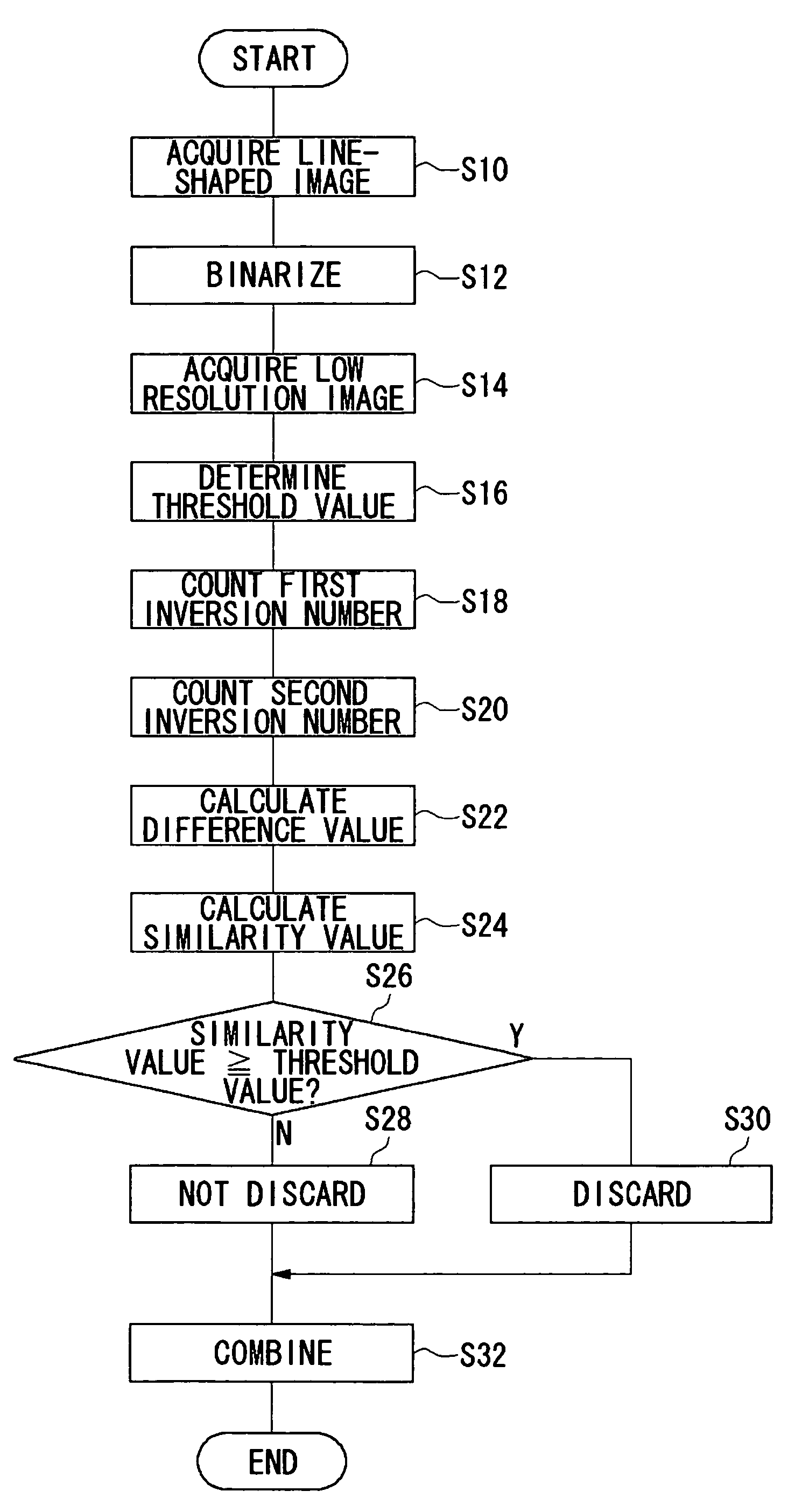
The present invention is about a system that uses multiple line-shaped images to capture biometric information. The system includes an image acquisition unit, a similarity value calculation unit, a compression unit, and a generation unit. The system can evaluate the similarity between different line-shaped images and compress them if they are similar to create a new image. This new image is then combined with other line-shaped images to create a final image of the human body part. The technical effect of this invention is that it allows for a more accurate and suitable image of a human body part for biometric information processing.

Problems solved by technology

However, a line sensor generally captures a large number of line-shaped images per unit time.

Method used


Image

  • Biometric information processing apparatus and biometric information processing method
  • Biometric information processing apparatus and biometric information processing method
  • Biometric information processing apparatus and biometric information processing method

Examples


first embodiment

[0025]A first embodiment relates to an apparatus for personal authentication by use of biometric information.

[0026]Generally, a technique for personal authentication by use of biometric information has been applied to compact devices such as a cellular phone. For example, in a technique for personal authentication by use of an image related to biometric information, it is desirable that a sensor, such as a line sensor, having a small installation area be mounted for acquiring the image. A line sensor acquires a fingerprint image as a plurality of strip-like images (also denoted as “line-shaped images”). The entire fingerprint image can be generated by combining the plurality of the strip-like images. A line sensor acquires a large number of line-shaped fingerprint images per unit time. Thus, if the moving speed of a finger is slow, the sensor acquires overlapping line-shaped images. Consequently, if all the acquired line-shaped images are combined, the combined image is caused to be...

second embodiment

[0057]A second embodiment also relates to an apparatus for personal authentication by use of biometric information.

[0058]Methods for personal authentication can be broadly classified into three categories. One method is authentication by a possession such as a key or an ID card. However, in the authentication by a possession, security is threatened by loss and theft. Another method is authentication by knowledge such as a password. However, the authentication by knowledge also has security problems caused by forgetfulness, peeping, or the like. An authentication method which has been receiving attention in recent years is biometric authentication by use of biometric information such as fingerprints, palm prints, faces, irises, voice prints, and vein patterns. In biometric authentication, the security concerns due to “loss” associated with the abovementioned authentication by a possession or knowledge is considerably suppressed. Further, since a user is “not required to keep” any obj...


PUM


Abstract

In order to acquire a suitable fingerprint image by correcting an elongated fingerprint image, a line sensor acquires fingerprint image as a plurality of line-shaped images. A computation unit computes a similarity value by use of an evaluation function for evaluating the degree of similarity between the line-shaped images. The similarity value represents the degree of similarity between a first line-shaped image and a second line-shaped image which serve as a similarity evaluation target and are included in the plurality of the line-shaped image. A compression unit compresses the first line-shaped image and the second line-shaped image when the similarity value is equal to or larger than a predetermined threshold value to generate a new line-shaped image. A generation unit generates the entire fingerprint image by combining the new line-shaped image with the other line-shaped images.

Description

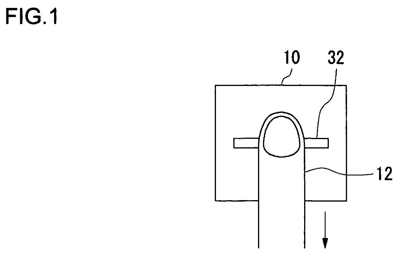
BACKGROUND OF THE INVENTION[0001]1. Field of the Invention[0002]The present invention relates to a technique for personal authentication by use of biometric information.[0003]2. Description of the Related Art[0004]A technique for personal authentication by use of biometric information has become widespread. There has been a demand that even a small portable device be provided with a function for acquiring biometric information. A line sensor is an example of a unit having such a function. For example, in a fingerprint authentication technique, a line sensor acquires an image of a fingerprint of a finger moving on the sensor as a plurality of line-shaped images. The entire fingerprint image can be generated by combining the plurality of line-shaped images acquired by the line sensor. A line sensor has a smaller sensor area as compared to a sensor capturing an entire fingerprint image at a time, thereby enabling space-saving upon mounting on a small portable device (see, for example, ...

Claims


Application Information

Patent Timeline
Patent Type & Authority Patents(United States)
IPC IPC(8): G06K9/00
CPCG06V40/1335
Inventor WATANABE, KEISUKEMASUDA, TATSUYAOHYAMA, TATSUSHISAITOH, HIROFUMITAKASAKI, YASUNARIOKUMURA, MASAYA
Owner SANYO ELECTRIC CO LTD
Learn More