
Aperture matched polyrod antenna

a polyrod antenna and polyrod technology, applied in the direction of leaky waveguide antennas, slot antennas, antennas, etc., can solve the problems of not measuring the response of the material to a plane wave, the speed of light in the focal spot of a focused beam system is not equal to the speed, and the inhomogeneity of manufacturing materials becoming significant sources of noise at high frequency, etc., to reduce the diameter of the gaussian beam, the effect of minimizing or reducing

Inactive Publication Date: 2011-02-15
ARIZONA STATE UNIVERSITY
View PDF6 Cites 226 Cited by
  • Summary
  • Abstract
  • Description
  • Claims
  • Application Information

AI Technical Summary

Benefits of technology

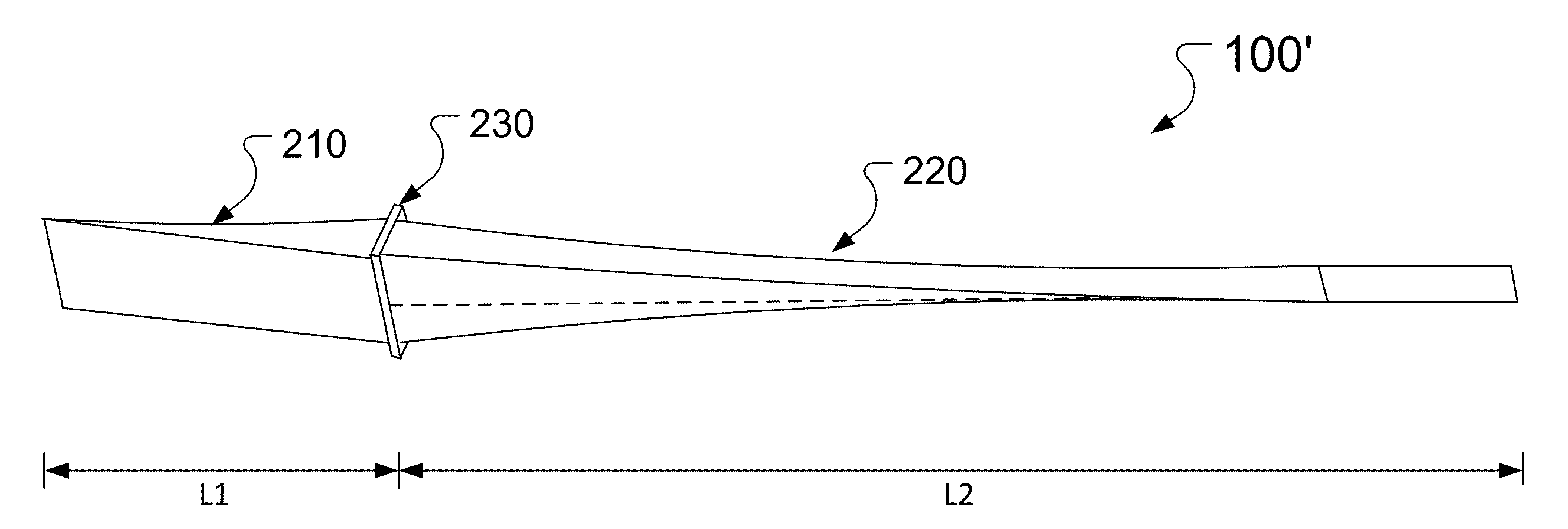
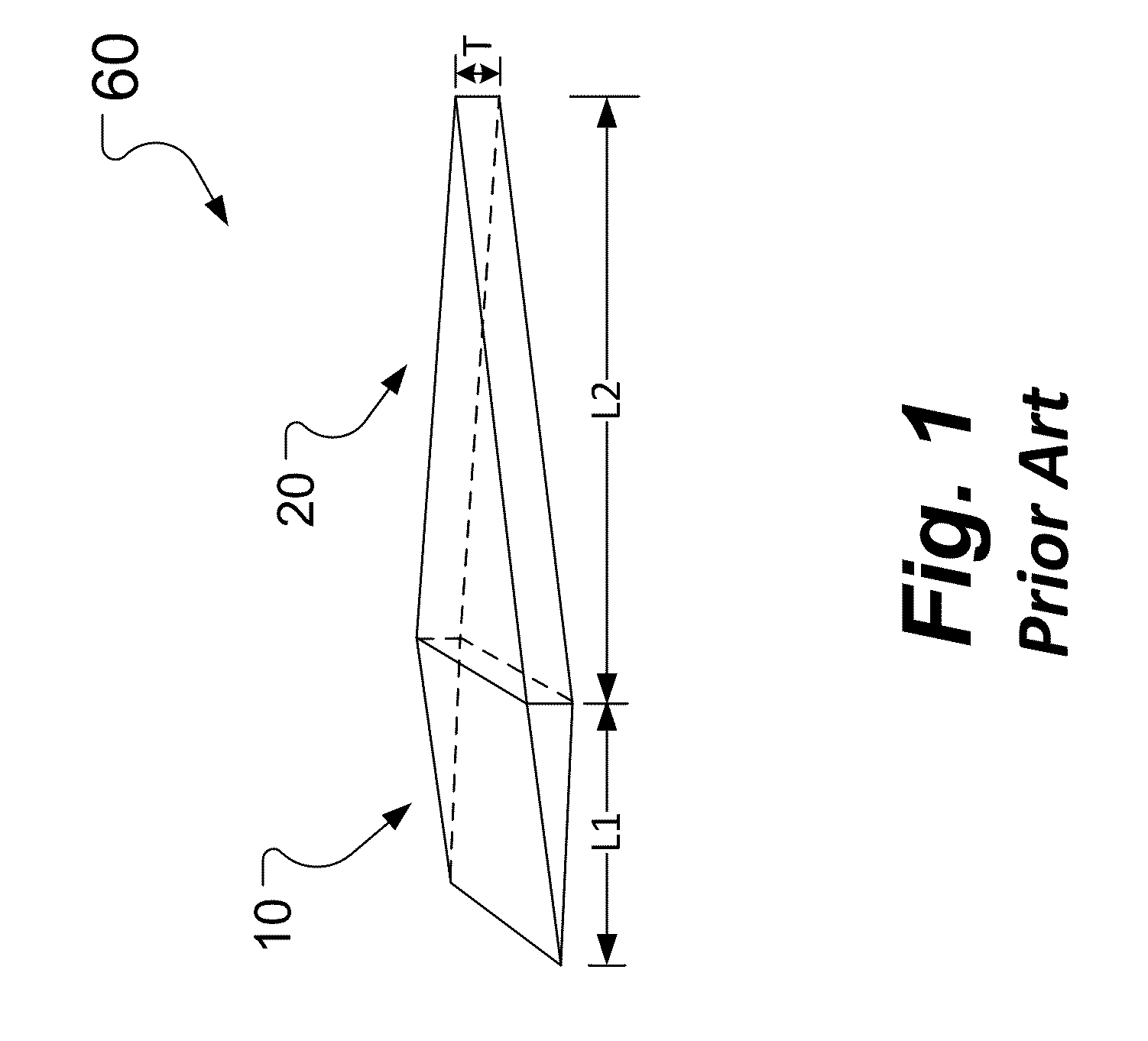
[0008]An aspect of an embodiment of the present invention is directed toward a dielectric polyrod that minimizes or reduces end reflection and phase variation across a beam of electromagnetic radiation, or specifically a Gaussian Beam, as well as minimizing or reducing the diameter of the Gaussian beam. In one embodiment, the dielectric polyrod includes a short tapered section, a long tapered section, and an intermediate section, where the short tapered section is extended between the intermediate section and a first end, and the long tapered section is extended between the intermediate section and a second end oppositely facing the first end, and the long tapered section is tapered along a curve.

Problems solved by technology

The problem with this approach is that the field at the aperture is not a plane wave and thus the response of the material to a plane wave is not being measured.
The problem with this approach is that by definition the size of the spot generated is a strong function of frequency so that if a region 3″ by 3″ is being examined at 2 GHz, the region shrinks to 0.3″ by 0.3″ at 20 GHz, thus any manufacturing inhomogeneities in the material become significant sources of noise at high frequency.
Another problem associated with the lens approach is the speed of light in the focal spot of a focused beam system is not equal to the speed of light in free space but is actually faster.

Method used


Image

  • Aperture matched polyrod antenna
  • Aperture matched polyrod antenna
  • Aperture matched polyrod antenna

Examples


Embodiment Construction

[0037]In the following detailed description, only certain exemplary embodiments of the present invention have been shown and described, simply by way of illustration. As those skilled in the art would realize, the described embodiments may be modified in various different ways, all without departing from the spirit or scope of the present invention. Accordingly, the drawings and description are to be regarded as illustrative in nature and not restrictive. Like reference numerals designate like elements throughout the specification.

[0038]Embodiments of the present invention provide a broadband method and / or a broadband antenna for extracting constitutive properties from an electromagnetic material measurement occurs under plane wave conditions, because the ability to mimic a plane wave condition at the material sample is highly desired. The ability to perform such a measurement in a small region allows designers and users of electromagnetic materials to reliably determine the constit...


PUM

PropertyMeasurementUnit
dielectric constantaaaaaaaaaa
frequencyaaaaaaaaaa

Abstract

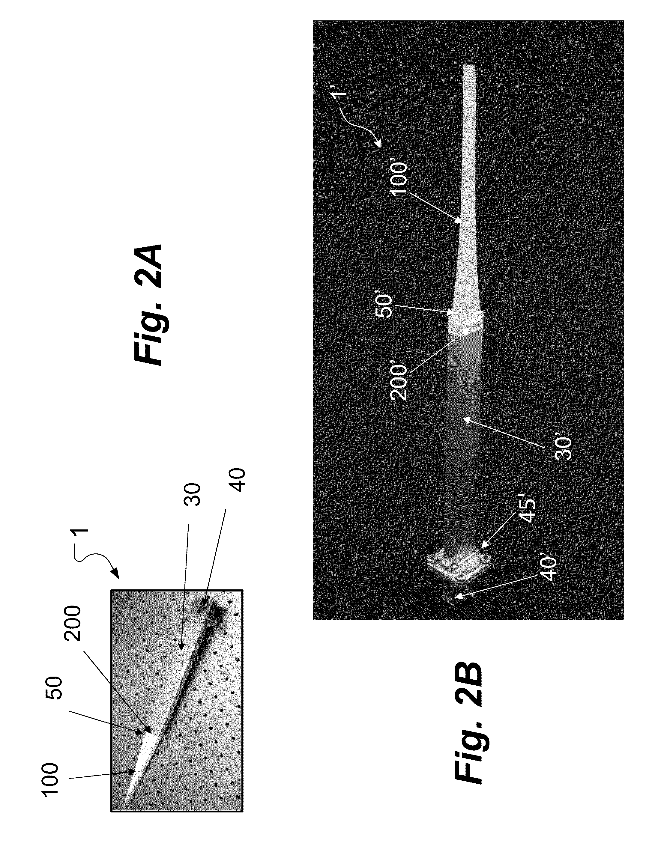
A dielectric polyrod having at least one tapered section, where a section exposed outside of the waveguide is tapered a long a curve that depends on the dielectric constant of the material used. The invention also relates to an aperture matched polyrod antenna which includes the same and an inductive tuning element used to achieve wideband impedance match and to create a Gaussian beam in the radiating near field of the antenna, suitable to mimic a small region plane wave.

Description

CROSS-REFERENCE TO RELATED APPLICATION[0001]This application claims priority to and the benefit of U.S. Provisional Application No. 60 / 871,548, filed Dec. 22, 2006, the entire contents of which are expressly incorporated herein by reference.FIELD[0002]Antennas with matched apertures are generally discussed herein, with particular discussions extended to an antenna with a polyrod and / or an incorporating an inductive obstacle element.BACKGROUND[0003]The measurements of surface impedance for small regions are typically done by two approaches. The first approach is to create a small aperture on a screen to pass through the electromagnetic signal and the second approach is to use a system of lenses to focus the signal.[0004]The first approach involves creating a small aperture on a metal screen through which the microwave field is coupled from a source on one side to a receiver on the other side. As such, when a material is placed over this aperture, the change in the transmitted field i...

Claims


Application Information

Patent Timeline
Patent Type & Authority Patents(United States)
IPC IPC(8): H01Q13/00
CPCH01Q13/24Y10T29/49016B33Y80/00
Inventor DIAZ, RODOLFOPEEBLES, JEFFREYGUO, YAN
Owner ARIZONA STATE UNIVERSITY
Learn More