Sliding lens cap

Inactive Publication Date: 2011-02-01
SHIN ZU SHING
View PDF11 Cites 3 Cited by
  • Summary
  • Abstract
  • Description
  • Claims
  • Application Information

AI Technical Summary

Benefits of technology

[0008]The main objective of the present invention is to provide a sliding lens cap that is easily operated and protects the lens. The sliding lens cap has a base, a driven cover, a driving cover, a linking bar and a sliding bracket. The base is mounted in front of the lens and has a lens hole aligning with the lens. The driven and driving covers are mounted pivotally to each other and selectively cover the lens hole. The linking bar and the sliding bracket are mounted pivotally to each other and are connected to the driven and driving covers. With such connection, the user opens and closes the covers by actuating the sliding bracket without touching the covers. Therefore, touching the lens is prevented.

Problems solved by technology

However, removed from the lens, the detachable cap may be mislaid, damaged or soiled.
The latter instance causing transfer of dirt and dust to the lens defeating objectives of the lens cap.
Although a string may connect the lens cap and lens, the lens cap may obscure a view of the lens, obstruct use of the camera or projector or be shaken, blown or knocked into the lens, damaging the lens and becoming a hazard in itself.
The former costing more than the latter and being susceptible to damage or wear and tear and requiring servicing.
Furthermore, incorrect operation of manual type lens caps may cause impact with and damage the lens.

Method used


Image

  • Sliding lens cap
  • Sliding lens cap
  • Sliding lens cap

Examples


Embodiment Construction

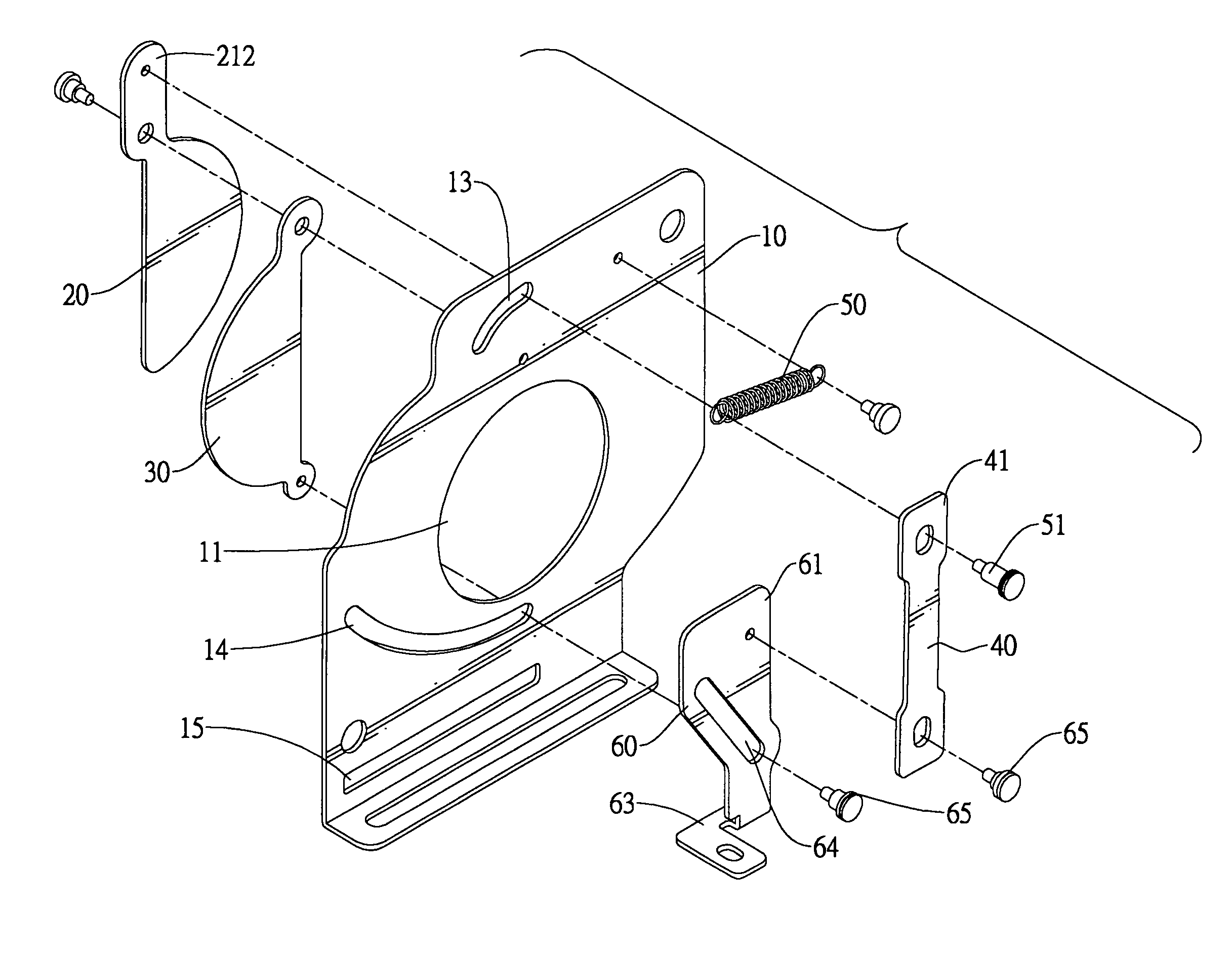
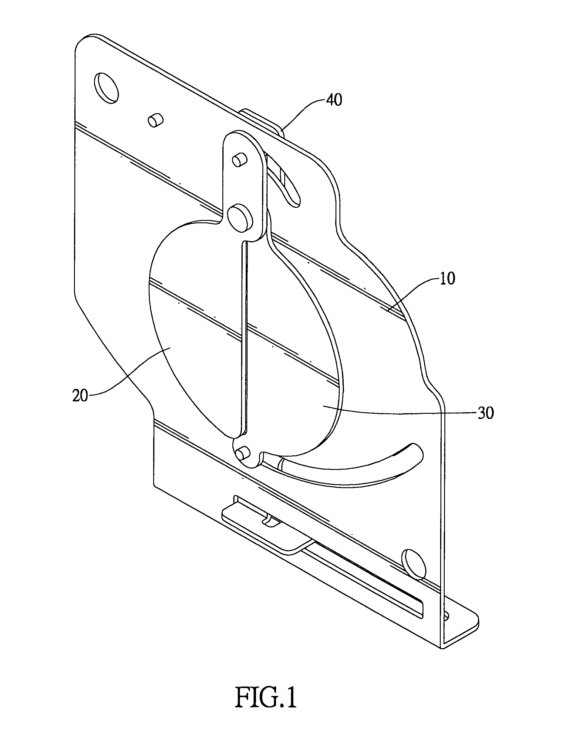
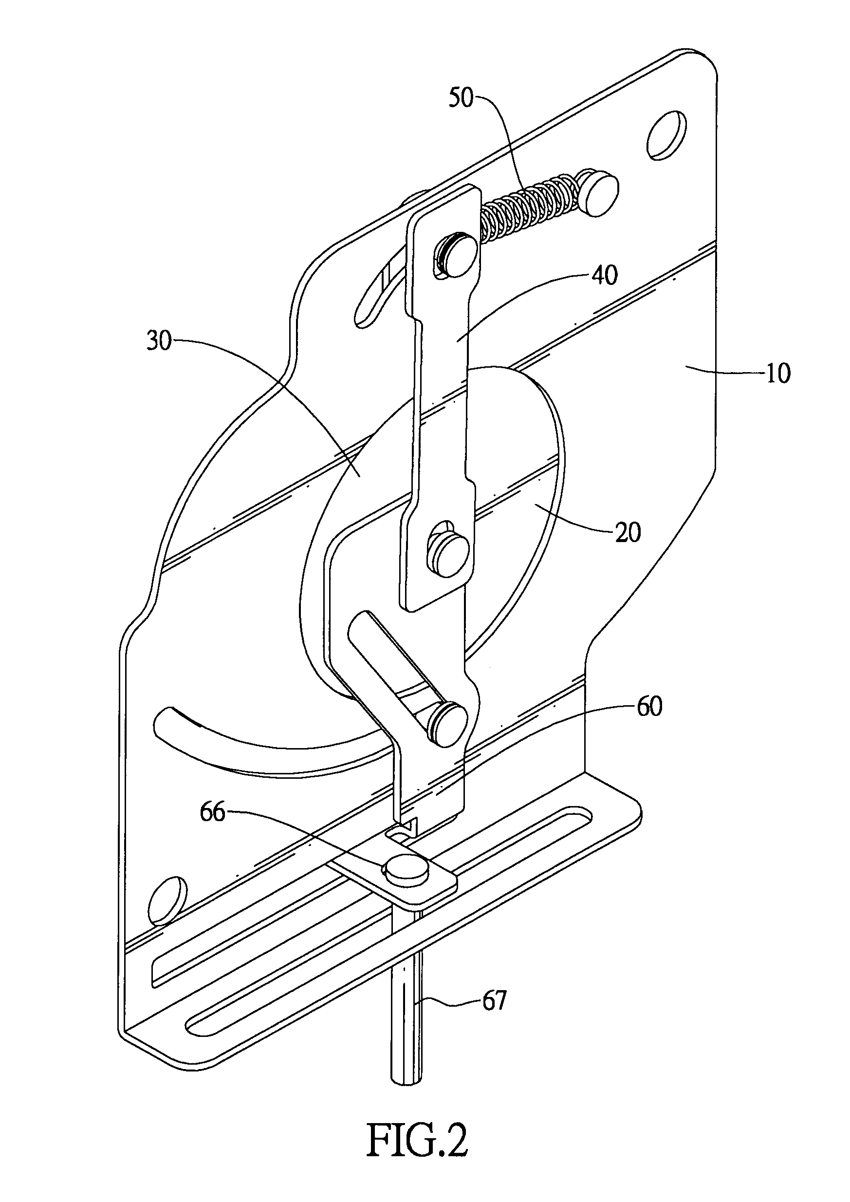
[0019]With reference to FIGS. 1 and 2, a sliding lens cap in accordance with the present invention comprises a base (10), a driven cover (20), a driving cover (30), a linking bar (40), a resilient element (50) and a sliding bracket (60).

[0020]With reference to FIGS. 3 and 4, the base (10) has a lens hole (11), a pivoting hole (12), a limiting slot (13), a guiding slot (14) and an actuating slot (15) formed therethrough. The lens hole (11) is formed between the limiting slot (13) and the guiding slot (14). The guiding slot (14) is formed between the actuating slot (15) and the lens hole (11). The pivoting hole (12) is formed between the limiting slot (13) and the lens hole (11). The lens hole (11) is circular. The limiting slot (13) and the guiding slot (14) are curved.

[0021]The driven cover (20) is mounted pivotally on a front surface of the base (10), may be semicircular, selectively caps part of the lens hole (11) and has a connecting tab (21). The connecting tab (21) extends out ...


PUM


Abstract

A sliding lens cap has a base, a driven cover, a driving cover, a linking bar and a sliding bracket. The base is mounted in front of the lens and has a lens hole aligning with the lens. The driven and driving covers are mounted pivotally to each other and selectively cover the lens hole. The linking bar and the sliding bracket are mounted pivotally to each other and are connected to the driven and driving covers. With such connection, a user opens and closes the covers by actuating the sliding bracket without touching the covers. Therefore, contact with the lens is prevented.

Description

BACKGROUND OF THE INVENTION[0001]1. Field of the Invention[0002]The present invention relates to a sliding lens cap, especially to a lens cap mounted slidably in front of a lens to properly cap the lens when not in use.[0003]2. Description of the Prior Arts[0004]Lenses for cameras, video cameras, projectors and the like are high precision devices. To prevent damage and soiling, when not in use the lens should be capped by a lens cap.[0005]Lens caps may be detachable lens caps, which selectively engages a perimeter of the lens. However, removed from the lens, the detachable cap may be mislaid, damaged or soiled. The latter instance causing transfer of dirt and dust to the lens defeating objectives of the lens cap. Although a string may connect the lens cap and lens, the lens cap may obscure a view of the lens, obstruct use of the camera or projector or be shaken, blown or knocked into the lens, damaging the lens and becoming a hazard in itself.[0006]Lens caps may also be sliding lens...

Claims


Application Information

Patent Timeline
IPC IPC(8): G03B11/04
CPCG03B11/04G03B11/043
Inventor LIN, SHU-MU
Owner SHIN ZU SHING
Why Eureka
Try Eureka