
Optical scanner and method of controlling optical scanner

a technology of optical scanner and optical scanner, which is applied in the direction of instruments, color television details, printing, etc., can solve the problems of lowering the performance of optical scanner, and achieve the effect of performing stable optical scanning and stable optical scanning

Inactive Publication Date: 2011-01-18
BROTHER KOGYO KK
View PDF15 Cites 3 Cited by
  • Summary
  • Abstract
  • Description
  • Claims
  • Application Information

AI Technical Summary

Benefits of technology

[0013]In this manner, the movable member of the oscillation-type optical scanning mechanism is oscillated at the resonance frequency and hence, even when the resonance frequency of the movable member of the oscillation-type optical scanning mechanism is changed due to an environment such as a temperature, a moisture or the like, or even when there exists difference in the resonance frequency attributed to the individual difference of the oscillation-type optical scanning mechanism, the optical scanner can perform stable optical scanning.
[0023]According to the present invention, the movable member of the oscillation-type optical scanning mechanism is oscillated at the resonance frequency and hence, even when the resonance frequency of the movable member of the oscillation-type optical scanning member is changed due to the environment such as the temperature or the moisture, or even when there exists the difference in resonance frequency attributed to the individual difference of the oscillation-type optical scanning mechanism, the optical scanner can perform stable optical scanning.

Problems solved by technology

Accordingly, when scanning of light beams is performed using the oscillation-type optical scanning mechanism which is driven in response to a drive signal based on the master clock and the BD signal explained in the Background Art, the resonance frequency of the movable member of the oscillation-type optical scanning mechanism and the scanning frequency given from the outside differ from each other and hence, there arises a case in which a sufficient scanning range is not acquired or stable horizontal scanning cannot be performed as a result of a fact that the distribution of a change width of the scanning range extends over a wide range thus giving rise to a possibility that the performance of the optical scanner is lowered.

Method used


Image

  • Optical scanner and method of controlling optical scanner
  • Optical scanner and method of controlling optical scanner
  • Optical scanner and method of controlling optical scanner

Examples


Embodiment Construction

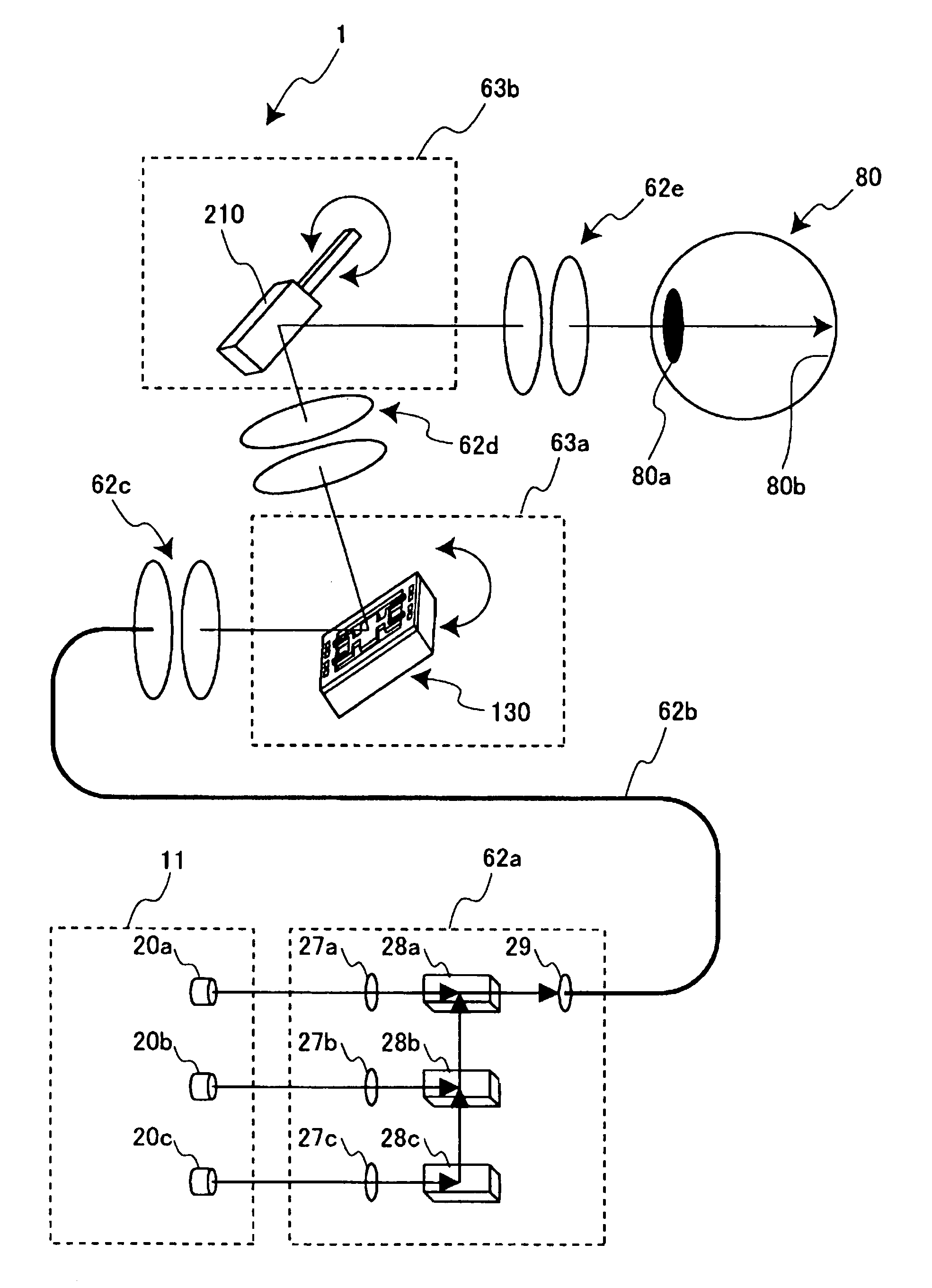
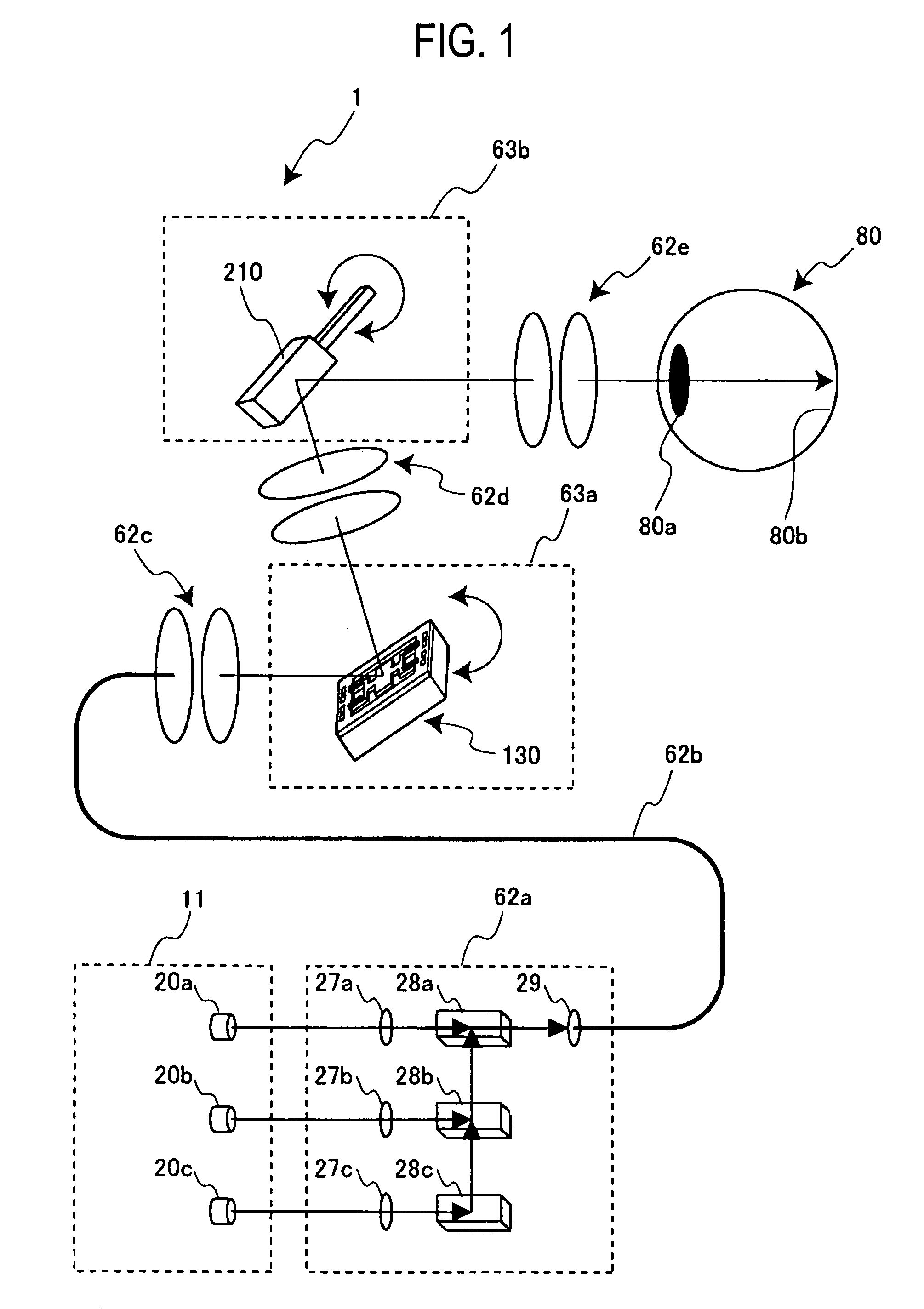
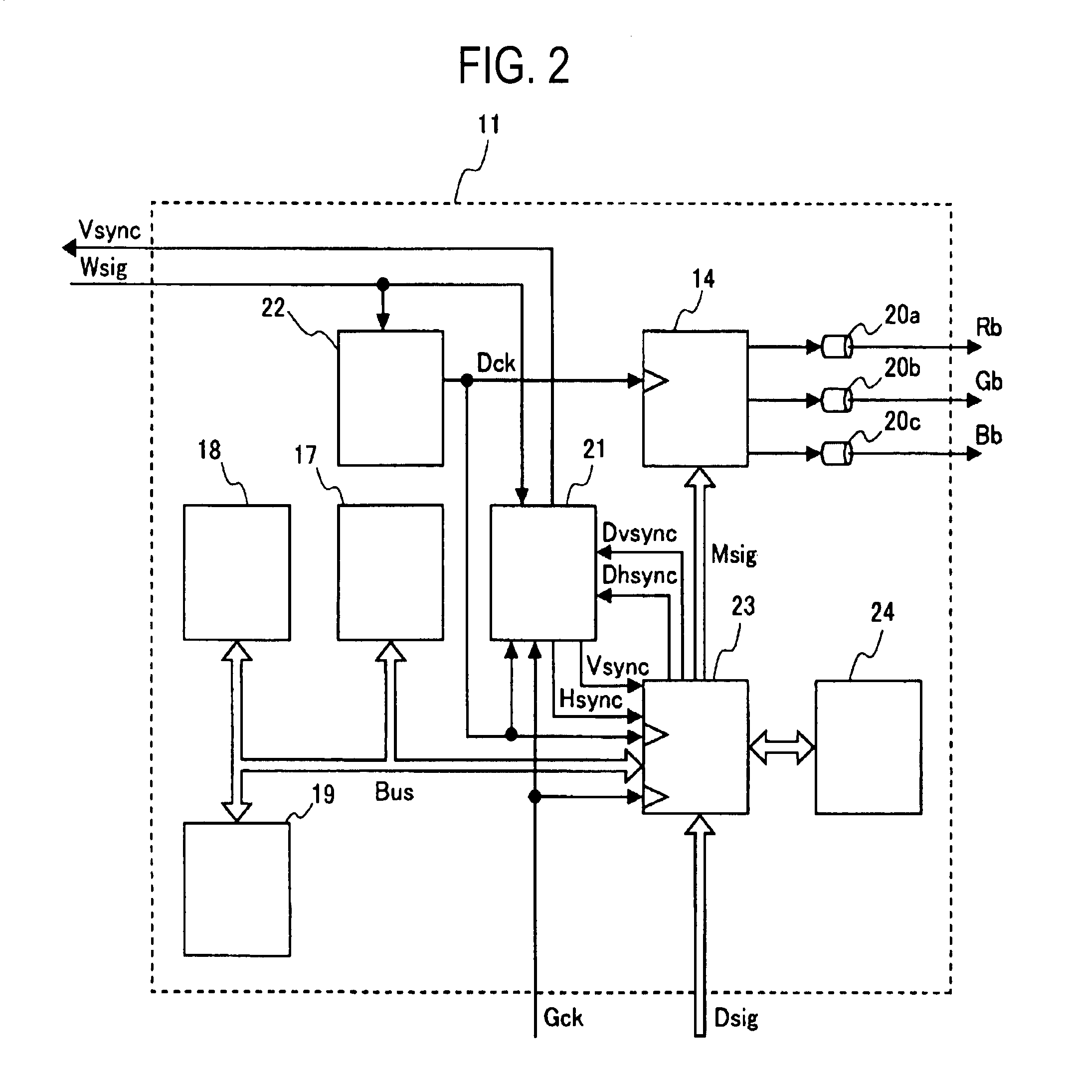
[0035]An optical scanner according to this embodiment which includes a light beam generating part which generates light beams in response to an image signal, an optical path part which guides the light beams to a projection screen, and an optical scanning part which changes the radiation direction of the light beams, wherein the optical scanning part includes an oscillation-type optical scanning mechanism which includes a movable member which resonates at a predetermined resonance frequency for changing the radiation direction of the light beams, a drive signal generator which generates a drive signal for allowing the oscillation-type optical scanning mechanism to resonate at the resonance frequency, and an oscillation signal generator which generates an oscillation signal in response to a change of the radiation direction of the light beams, and the light beam generating part includes a dot clock generator which generates a dot clock which becomes the reference of time-series proce...


PUM


Abstract

An optical scanner has an oscillation-type optical scanning mechanism which includes a movable member which resonates at a predetermined resonance frequency, a drive signal generator which generates a drive signal for allowing the movable member to resonate at the resonance frequency, and an oscillation signal generator which generates an oscillation signal in response to a change of the radiation direction of the light beams. Here, the oscillation signal generator includes a dot clock generator which generates a dot clock which becomes the reference of time-series processing by setting a frequency of the oscillation signal as a reference frequency.

Description

BACKGROUND OF THE INVENTION[0001]The present invention relates to an optical scanner and a method of controlling the optical scanner, and more particularly to an optical scanner which scans light beams by oscillating a movable member at intrinsic resonance frequency thereof and a control method of the optical scanner.[0002]An optical scanner which is represented by a laser beam printer or a projector which projects an image by scanning light beams has been conventionally used in various industrial fields. Such an optical scanner adopts an optical scanning mechanism which changes the direction of light and, recently, as a type of the mechanism, an oscillation-type optical scanning mechanism has been attracting attentions from a viewpoint of miniaturization of the device.[0003]In one conventional example of the oscillation-type optical scanning mechanism, light beams are scanned such that an oscillating body having a reflecting mirror portion is oscillated so as to change the reflecti...

Claims


Application Information

Patent Timeline
Patent Type & Authority Patents(United States)
IPC IPC(8): H04N1/04
CPCB41J2/473G02B26/0858G02B26/101H04N9/3129A61B3/1225
Inventor SAKAKIBARA, MASAHIRO
Owner BROTHER KOGYO KK
Learn More