
Table assembly for patient transfer device

a technology for transferring devices and tables, which is applied in the direction of wheelchairs/patient conveyancing, transportation and packaging, nursing beds, etc., can solve the problems of exacerbated problems, unable to use devices in all settings, and the design of rotating belts, so as to facilitate and comfortably acquire, transport and deliver patients.

Active Publication Date: 2011-01-04
MEDIGLIDER
View PDF29 Cites 9 Cited by
  • Summary
  • Abstract
  • Description
  • Claims
  • Application Information

AI Technical Summary

Benefits of technology

It is another object of the present invention to provide such a table assembly that can adjust the upper table geometry to more easily and comfortably acquire, transport and deliver a patient.
It is yet another object of the present invention to provide a table assembly for a patient transfer device that does not require clearance space under the patient's bed or table during operation.

Problems solved by technology

There can still be problems, however, in getting a patient from a bed or other support surface onto a stretcher or gurney.
This problem is exacerbated when the patient is unusually heavy.
This approach can still be difficult if the patient is uncooperative (i.e., unconscious), and can further be very uncomfortable even if the patient is cooperative, due to the frictional engagement of the tray with the body or the lack of firm support by the sheet.
There are still several serious problems with the counter-rotating belt designs.
Because of this limitation, such devices cannot be used in all settings, i.e., wherein there is insufficient clearance space under the bed or table (a situation becoming more common as more accouterments are added to beds and tables that occupy the space underneath).
These devices further only allow loading and unloading along one side of the device, which can present problems when the patient is not suitably oriented (head-to-feet) on the device with respect to the bed or table.
Designs such as that shown in the '321 patent are also not particularly comfortable as there is only a thin layer of the belt interposed between the patient and the hard surface of the metal support trays.
Moreover, hospitals are becoming increasingly concerned with potential contamination from patient fluids, and the prior art belt-type transfer devices are difficult if not impossible to properly clean.
Another problem relates to the initial impact of the trays as they acquire a patient.
The height of the trays and the large diameter edge rollers in the '321 design present an abrupt bump along the patient's side during acquisition, and result in a similar bumpy delivery of the patient back to a support surface.
The tray can be inclined, for example as shown in U.S. Pat. No. 4,914,769, but a large angle of inclination makes it more difficult to acquire the patient and can increase patient discomfort during loading and unloading.
It is also more likely that a patient will roll off the table assembly if the edge portions can incline downward.

Method used


Image

  • Table assembly for patient transfer device
  • Table assembly for patient transfer device
  • Table assembly for patient transfer device

Examples


Embodiment Construction

)

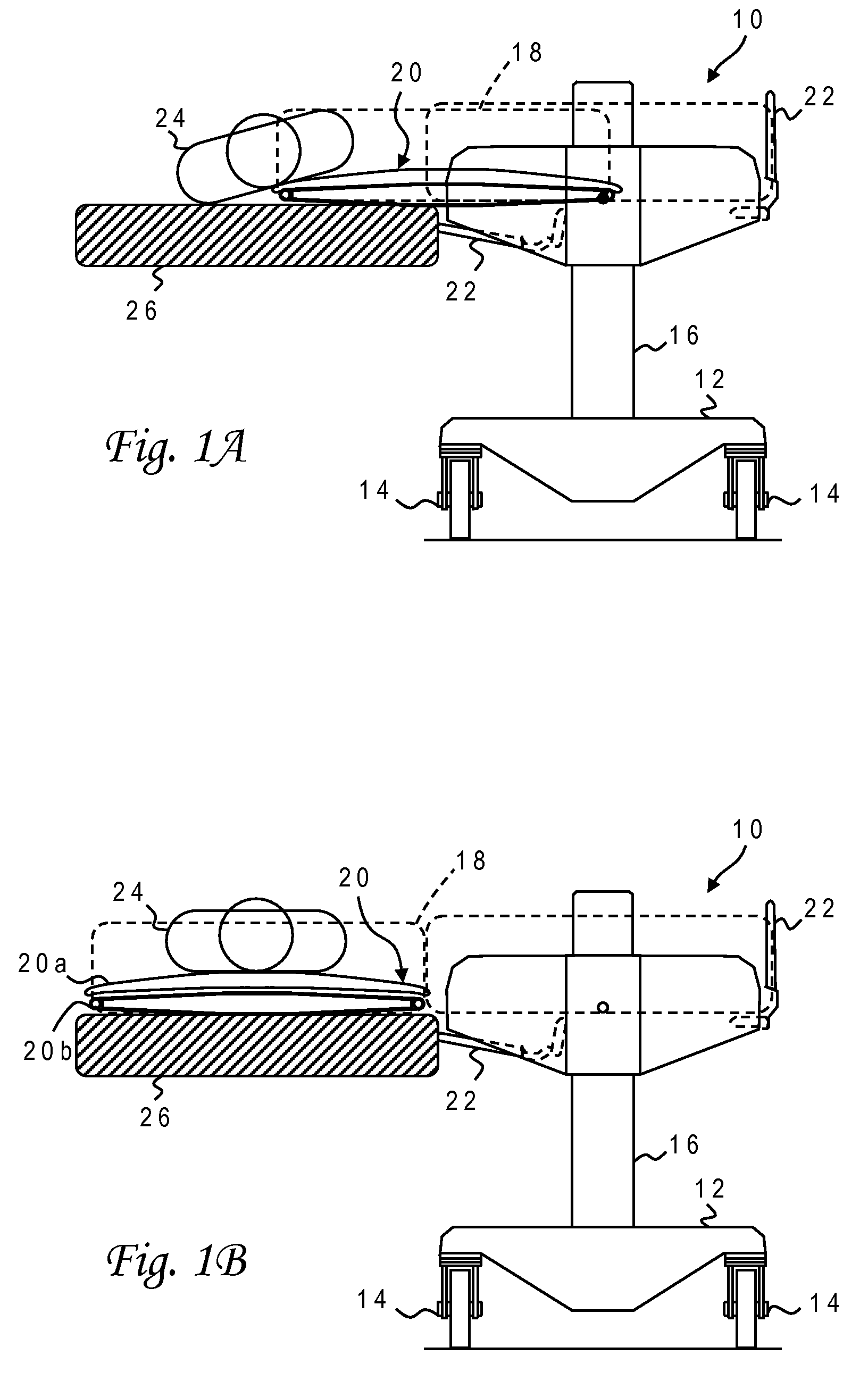
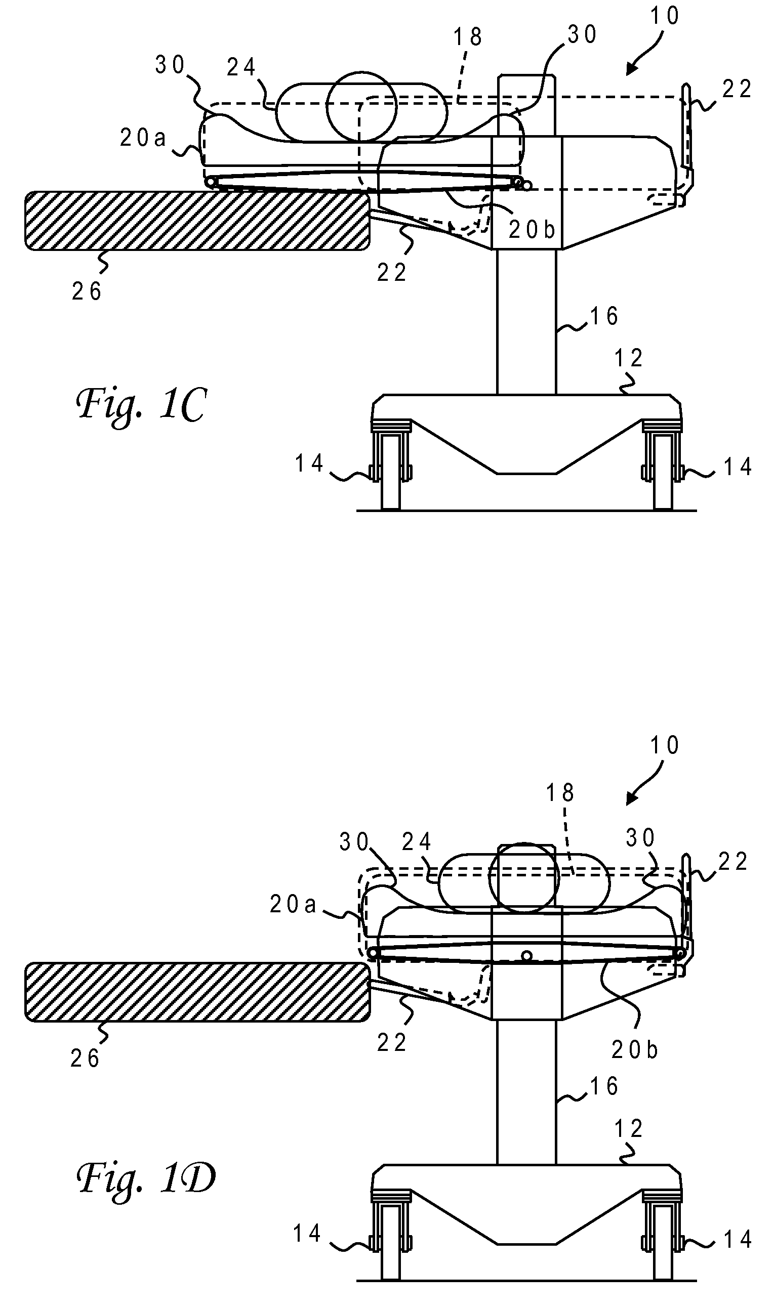
With reference now to the figures, and in particular with reference to FIGS. 1A-1D, there is depicted one embodiment 10 of a patient transfer device constructed in accordance with the present invention. Patient transfer device 10 is generally comprised of a frame or base 12 mounted on four or more wheels or casters 14, two vertical support members or columns 16 mounted on base 12, a horizontal slide assembly 18 attached to support columns 16, a table assembly 20 attached to slide assembly 18, and side rails 22 attached to support columns 16.

FIG. 1A illustrates a patient acquisition position of slide assembly 18 and table assembly 20 wherein a leading edge of table assembly 20 has crawled about halfway under the patient 24 who is resting on a bed or other support surface 26. Table assembly 20 includes an upper table 20a and a lower table 20b each of which is surrounded by a respective endless belt or web. In the patient acquisition position, upper table 20a is in forcible contact wi...


PUM


Abstract

A table assembly for a patient transfer device has upper and lower tables surrounded by belts which counter-rotate as the table assembly moves between a patient and a supporting surface such as a bed. The table assembly includes integrated means for laterally retracting side plates of the upper table while adjusting incident angles of the side plates and vertically separating the upper table from the lower table. Guide slots in end plates fixed to a slide assembly retain positioning posts attached to ends of the side plates. The slots are inclined upwardly toward a centerline of the table assembly at different angles. A crank moves the side plates using a rotating disk attached to a central frame of the upper table and linkage arms with one end pivotally attached to a peripheral region of the disk and another end pivotally attached to one of the positioning posts.

Description

BACKGROUND OF THE INVENTION1. Field of the InventionThe present invention generally relates to devices for moving objects, and more particularly to a tray or table assembly for a patient transfer device wherein the table assembly includes upper and lower tables having counter-rotating, endless belts.2. Description of the Related ArtA wide variety of products have been designed to move objects from one location to another and, in particular, transfer mobility-impaired individuals such as patients. In a hospital setting, patients must often be transported from their beds to an examination table or operating table, and back again. Basic devices for transferring patients include stretchers that are carried manually by two attendants, and wheeled gurneys that can more easily be handled by a single attendant.There can still be problems, however, in getting a patient from a bed or other support surface onto a stretcher or gurney. If the patient is cooperative and not injured or disabled, i...

Claims


Application Information

Patent Timeline
Patent Type & Authority Patents(United States)
IPC IPC(8): A61G7/10
CPCA61G7/1019A61G7/1032A61G7/1057A61G7/1046A61G2203/723A61G2200/32
Inventor PATTERSON, RICHARD A.GRAVELL, LAWRENCE R.
Owner MEDIGLIDER
Learn More