LCD with source driver and data transmitting method thereof

a liquid crystal display and source driver technology, applied in the direction of instruments, static indicating devices, etc., can solve the problem of higher cost of lcd, and achieve the effect of low cost and lower output loading of timing controllers

Inactive Publication Date: 2010-11-30
HIMAX TECH LTD
View PDF4 Cites 2 Cited by
  • Summary
  • Abstract
  • Description
  • Claims
  • Application Information

AI Technical Summary

Benefits of technology

[0007]The invention is directed to a liquid crystal display (LCD) and a data transmitting method thereof, in which a fewer buses are utilized for data transmission, and a source driver of the invention may be applied to the conventional LCD architecture according to a special data mapping method. Thus, the LCD having the source driver and the data transmitting method according to the invention have the advantages of the low cost and the lower output loading of a timing controller, and the source driver of the invention may also be advantageously applied to the conventional LCD architecture.

Problems solved by technology

The buses occupy a larger layout area on a printed circuit board (PCB) so that the cost of the LCD is higher.

Method used


Image

  • LCD with source driver and data transmitting method thereof
  • LCD with source driver and data transmitting method thereof
  • LCD with source driver and data transmitting method thereof

Examples


first embodiment

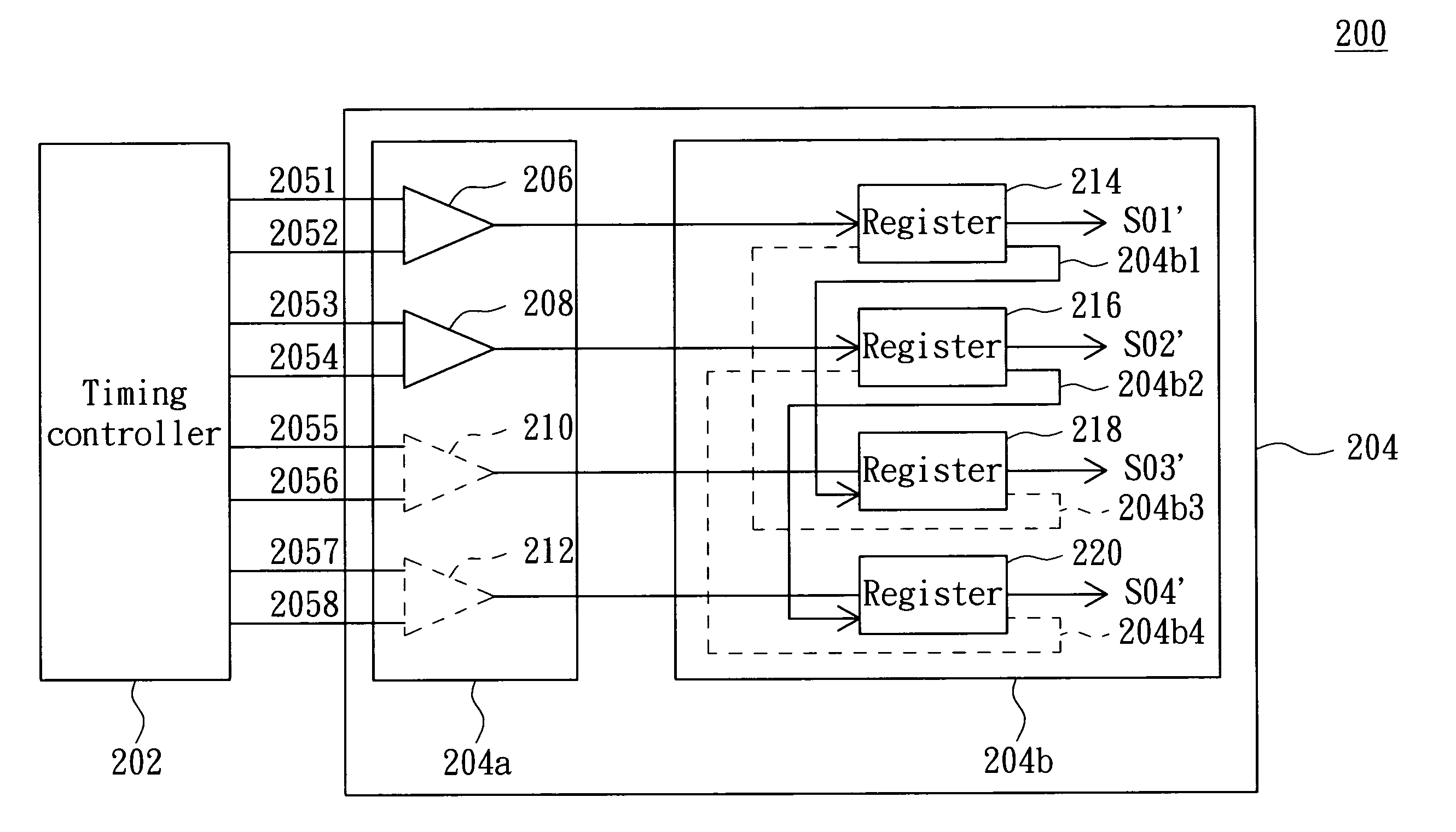
[0025]FIG. 3A shows a circuit layout of the timing controller 202 and the source driver 204 when the source driver 204 operates in the first mapping operation mode. As shown in FIG. 3A, when the source driver 204 operates in the first mapping mode, the receiving units 210 and 212 and the transmission paths 204b3 and 204b4 are disabled (the disabled receiving units 210 and 212 and the disabled transmission paths 204b3 and 204b4 are represented by dashed lines), and the transmission paths 204b1 and 204b2 are enabled. Thus, the timing controller 202 only can output the red sub-pixel data to the receiving units 206 and 208 through the buses 2051 to 2054, and the registers 214 and 216 are respectively coupled to the registers 218 and 220 in series.

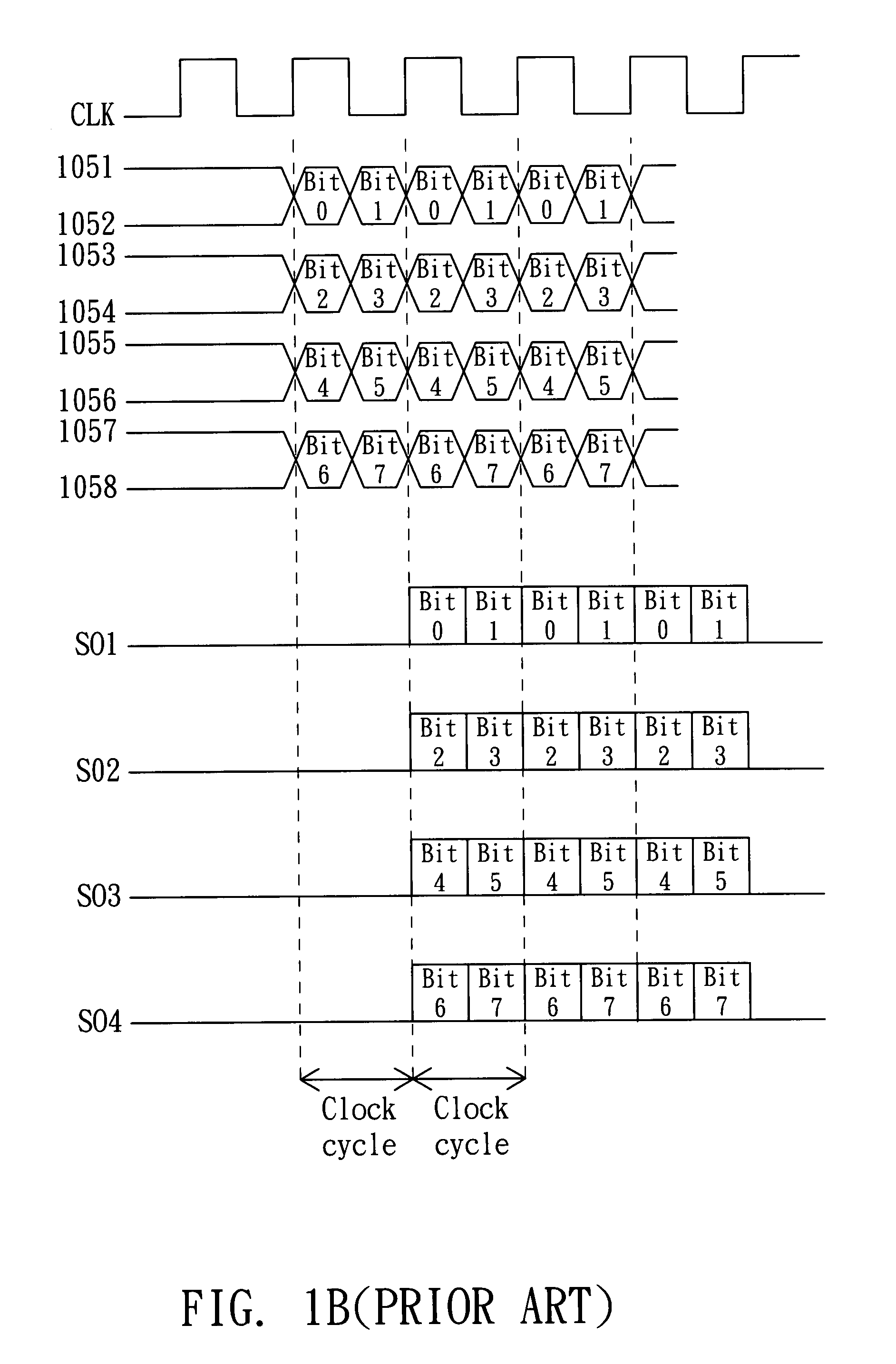
[0026]FIG. 3B shows timing charts of the bit data on the buses 2051 to 2054 when the source driver 204 operates in the first mapping operation mode.

[0027]At a rising edge of a first clock cycle of the clock signal CLK, the timing controller 202...

second embodiment

[0043]FIG. 6A shows a circuit layout of the timing controller 202 and the source driver 204 when the source driver 204 operates in the second mapping operation mode. As shown in FIG. 6A, the source driver 204 operating in the second mapping operation mode differs from the source driver 204 operating in the first mapping operation mode because the disabled receiving units and data transmission paths are different from each other. Meanwhile, the bit data Bit0 to Bit7 outputted from the timing controller 202 are received through different buses. When the source driver 204 operates in the second mapping operation mode, the receiving units 206 and 208 and the transmission paths 204b1 and 204b2 are disabled (the disabled receiving units 206 and 208 and the disabled transmission paths 204b3 and 204b4 are represented by dashed lines). In addition, the transmission paths 204b3 and 204b4 are enabled.

[0044]FIG. 6B shows timing charts of the bit data on the buses 2055 to 2058 when the source dr...


PUM


Abstract

A data transmitting method for inputting a data signal to an electronic device. The data signal includes first and second sets of data, and the electronic device includes first to fourth receiving units and corresponding first to fourth registers. The transmitting method includes the following steps. First, the first and second receiving units are disabled. Then, the first set of data is inputted to the electronic device through the third and fourth receiving units and stored in the third and fourth registers during a first clock cycle of a clock signal. Thereafter, the second set of data is inputted to the electronic device through the third and fourth receiving units and stored in the third and fourth registers while the first set of data stored in the third and fourth registers is inputted to the first and second registers during a second clock cycle of the clock signal.

Description

[0001]This application claims the benefit of Taiwan application Serial No. 095128890, filed Aug. 7, 2006, the subject matter of which is incorporated herein by reference.BACKGROUND OF THE INVENTION[0002]1. Field of the Invention[0003]The invention relates in general to a data transmitting method of a liquid crystal display (LCD), and more particularly to a data transmitting method of a LCD capable of reducing the number of buses between a source driver and a timing controller.[0004]2. Description of the Related Art[0005]FIG. 1A (Prior Art) is a partial circuit diagram showing a conventional LCD 100. FIG. 1B (Prior Art) shows timing charts of some signals of the LCD 100 of FIG. 1A. Referring to FIGS. 1A and 1B, the LCD 100 includes a timing controller 102, buses 1051 to 1058, a source driver 104 and a pixel array (not shown). The source driver 104 includes a receiver 104a and a line buffer 104b. The pixel array has pixels each including red, green and blue sub-pixels. Sub-pixel data ...

Claims


Application Information

Patent Timeline
Patent Type & Authority Patents(United States)
IPC IPC(8): G09G3/36
CPCG09G3/2092G09G3/3685
Inventor CHEN, CHIEN-RUCHEN, YING-LIEHBU, LIN-KAI
Owner HIMAX TECH LTD
Why Eureka
Try Eureka