Drainage catheter with locking hub

a technology of drainage catheter and hub, which is applied in the direction of catheters, suction devices, other medical devices, etc., can solve the problems of affecting the drainage effect of the patient, so as to facilitate the retention of the catheter and facilitate the repositioning of the catheter. , the effect of convenient suture securemen

Active Publication Date: 2010-11-02
MERIT MEDICAL SYST INC
View PDF68 Cites 19 Cited by
  • Summary
  • Abstract
  • Description
  • Claims
  • Application Information

AI Technical Summary

Benefits of technology

[0010]According to the present invention the drainage catheter hub includes a bistable locking mechanism for securing a suture. In one embodiment, the bistable locking mechanism facilitates convenient securement of the suture which in turn facilitates retention of the catheter within a patient's body. The bistable locking mechanism allows convenient releasing of the suture to facilitate repositioning of the catheter in the patient's body and removal of the catheter from the patient's body, in a safe and convenient manner. In one exemplary embodiment, the drainage catheter comprises a hub having a bistable locking mechanism positioned therein. The bistable locking mechanism can include: (i) an elongate member; (ii) a ball joint component member; and (iii) a socket component member.
[0011]The present invention also relates to a release mechanism which reliably enables a drainage tip of the catheter to relax allowing the tip of the catheter to be removed from or repositioned within the patient's body. In one embodiment of the present invention, a suture extends from within the hub, through a portion of the bistable locking mechanism, along the length of the catheter tube, exits through the catheter tip, and is secured to and terminates at a securing wire at an attachment point on the distal portion of the tube. When the bistable lock is in an unlocked configuration, a practitioner can pull the proximal end of the suture to cause the drainage tip to flex toward the tube in a substantially curved fashion. The practitioner can then depress the bistable locking mechanism into a locked configuration to secure the suture inside the bistable locking mechanism. Securing the suture facilitates retention of the drainage tip in the looped or curved configuration. Bodily fluid then enters the drainage tip, travels through the tube, and exits through a proximal portion of the tube.
[0012]When repositioning of the catheter is required the practitioner can displace the bistable locking mechanism into an unlocked or relaxed first position, such that the suture is no longer secured. The relaxed suture thus allows for straightening of the drainage tip of the catheter tube to allow the practitioner to reposition the catheter. Once the catheter is appropriately repositioned, the practitioner can return the bistable locking mechanism back to the locked position to effectively retain the position of the catheter in the patient.

Problems solved by technology

If the fluid is not removed further complications in the patient can occur such as rupturing or infection of the tissue.
Unfortunately, securing the catheter hub in this manner can be somewhat insecure and inconvenient, especially if the catheter is to remain in place for an extended period of time.
In the event that additional manipulation or repositioning of the catheter tube must be utilized, it can be difficult to unwrap the suture from the hub for proper manipulation of the length of catheter.
Unfortunately, the curved conformation of the tip relative to the catheter tube makes it difficult to remove the drainage catheter from its drainage position.
In particular, removing the drainage catheter while the tip is still in an inwardly flexed position can cause the drainage catheter to tear or otherwise damage bodily tissue.
Where the suture has been wrapped to maintain the curved configuration of the tip of the drainage catheter, unwrapping of the suture can be difficult and time consuming.
Furthermore, when the practitioner releases the suture, the flexible tip on the conventional catheter will not fully release in a manner that allows manipulation of the catheter tip into a substantially straight position.

Method used


Image

  • Drainage catheter with locking hub
  • Drainage catheter with locking hub
  • Drainage catheter with locking hub

Examples


Embodiment Construction

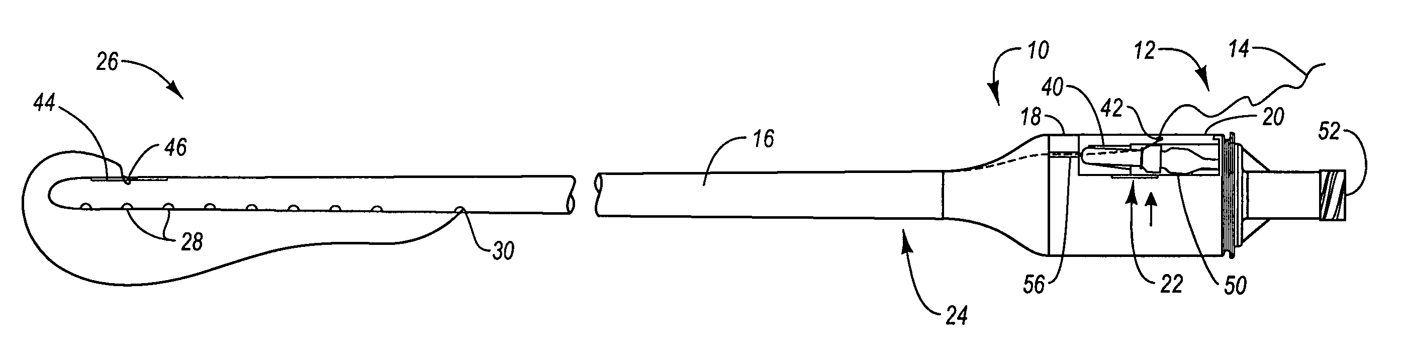
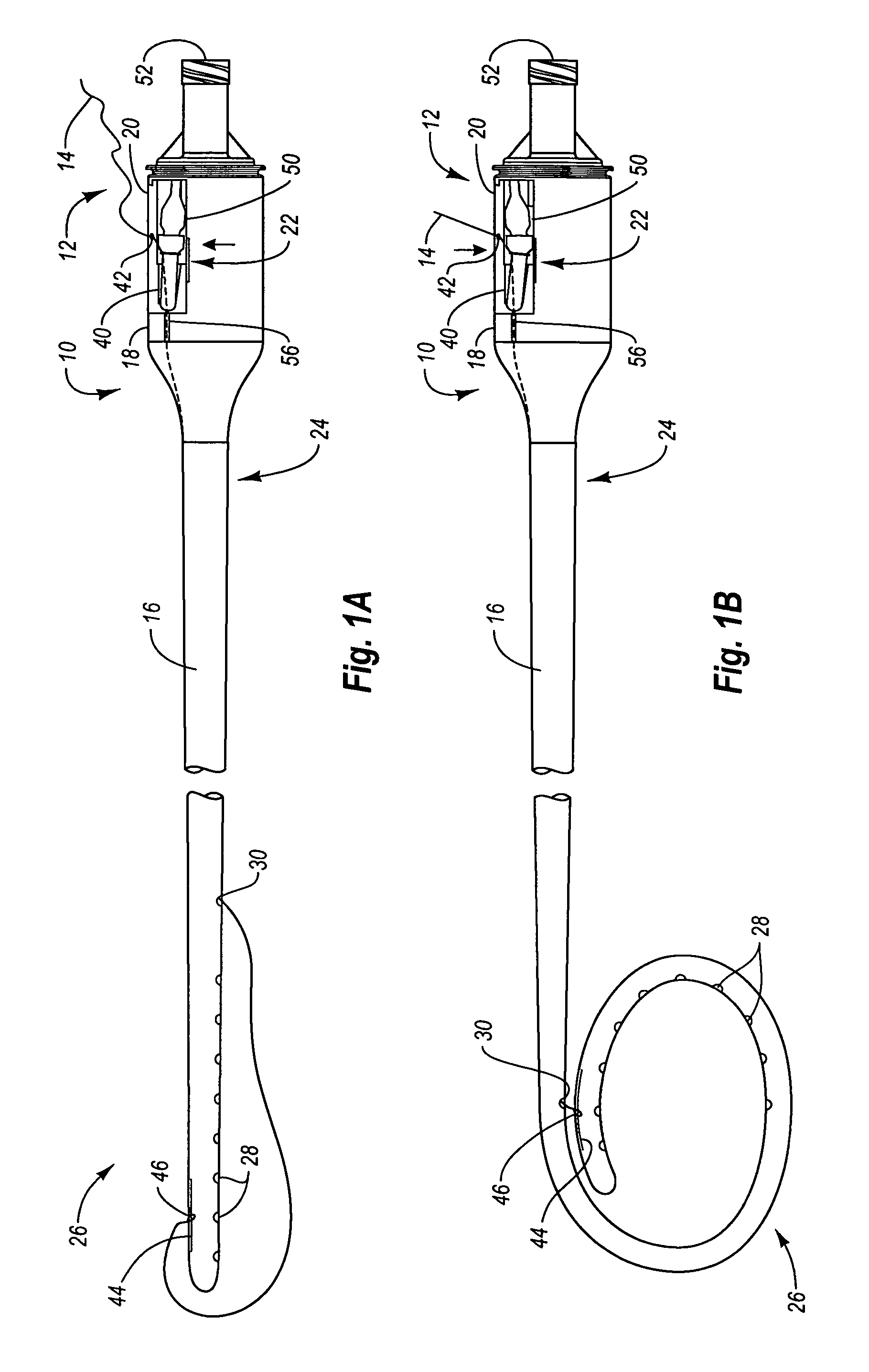
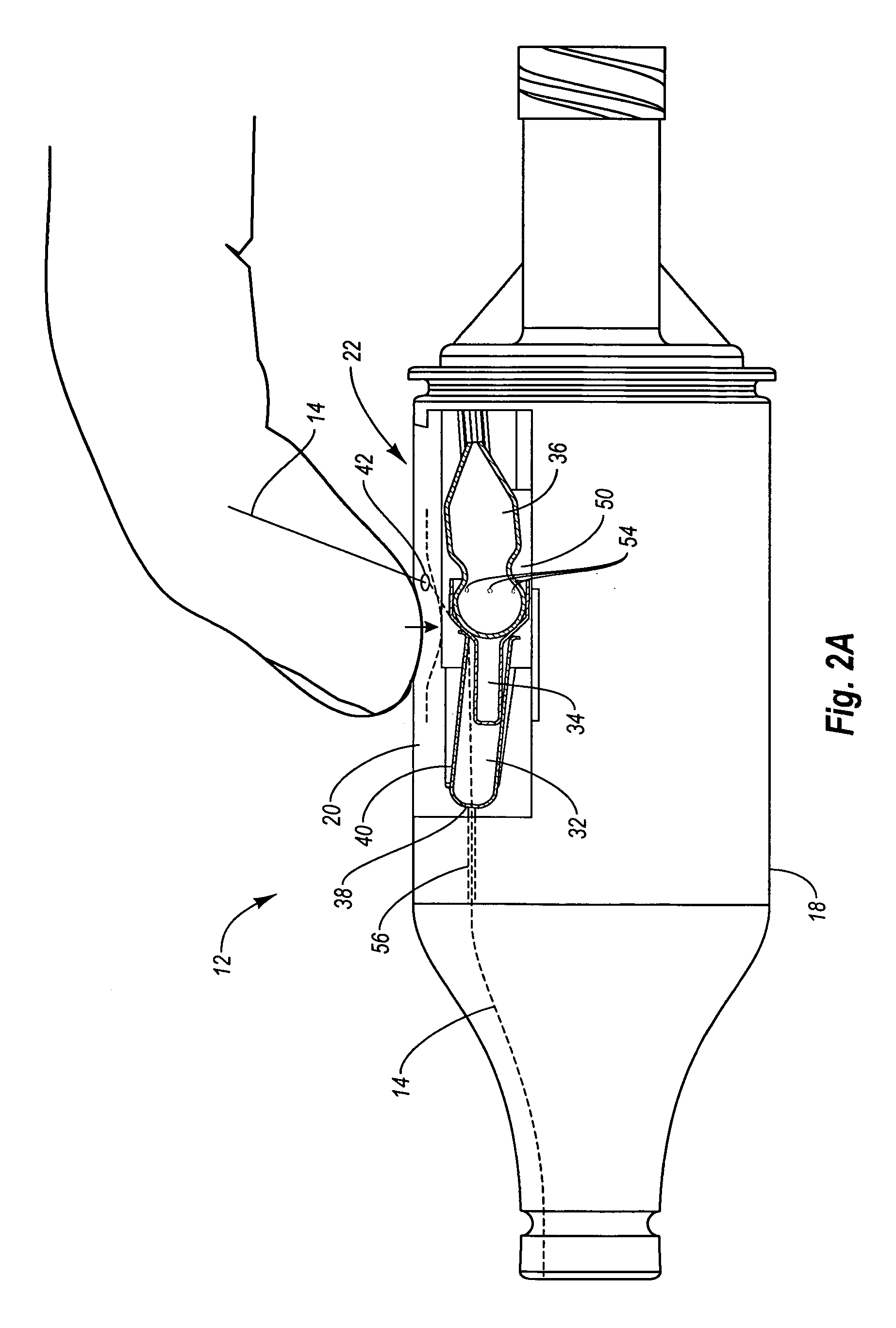
[0021]The present invention relates to a drainage catheter having a three-part bistable locking mechanism positioned within the hub of the catheter for securing a suture. The bistable locking mechanism facilitates convenient securement of the suture, which in turn facilitates retention of the catheter within a patient's body. The bistable locking mechanism is also adapted to provide convenient releasing of the suture to facilitate: (i) management of the position of the catheter once it is inserted into the patient's body; and (ii) removal of the catheter from a patient's body, in a safe and convenient manner. In one exemplary embodiment, the drainage catheter comprises a hub having a bistable locking mechanism positioned within the housing of the hub. The bistable locking mechanism is configured to selectively secure and release a suture that is positioned adjacent or within a portion of the bistable locking mechanism. The bistable locking mechanism is adapted to have two equilibriu...


PUM


Abstract

A drainage catheter hub for use in connection with a drainage catheter to receive and secure a suture therein, wherein the hub includes: (i) a housing having a channel to accommodate the suture therein; (ii) a bistable locking mechanism positioned in the housing and being adapted to provide selective securement of the suture; and (iii) a resilient outer layer utilized in connection with the bistable locking mechanism and coupled to the housing. The bistable locking mechanism is configured to: (i) allow movement of the suture when the bistable locking mechanism is in a first position; and (ii) minimize axial movement of the suture when the bistable locking mechanism is in a second position. The resilient outer layer is adapted to allow a user to actuate the bistable locking mechanism between the first and second positions to selectively secure and release the suture.

Description

BACKGROUND OF THE INVENTION[0001]1. The Field of the Invention[0002]This invention relates to systems and apparatus for draining bodily fluid from a patient. In particular, the present invention relates to drainage catheters, and more specifically, to a drainage catheter hub apparatus for selectively securing or releasing a suture.[0003]2. Background and Relevant Art[0004]Drainage catheters are used in a variety of medical settings for draining fluids from a patient's body. For example, a patient may suffer an injury, or have a medical condition where a bodily tissue stores an excess amounts of fluid, such as blood, or other bodily serum. If the fluid is not removed further complications in the patient can occur such as rupturing or infection of the tissue. Accordingly, drainage catheters have been developed to remove these fluids from the patient, to either relieve pressure, or to otherwise ensure the fluid build up does not result in tissue injury.[0005]Conventional drainage cathe...

Claims


Application Information

Patent Timeline
Patent Type & Authority Patents(United States)
IPC IPC(8): A61M31/00A61M27/00A61M37/00
CPCA61M25/0017A61M25/0147A61M25/0097A61M25/007A61M2025/0163
Inventor ACCISANO, III, NICHOLAS GERALDLAMPROPOULOS, FRED
Owner MERIT MEDICAL SYST INC
Why Eureka
Try Eureka