
Connector for connecting conductors of a cable to flat conductors of a photovoltaic cell

a technology of photovoltaic cells and connectors, which is applied in the direction of pv power plants, coupling device connections, contact members penetrating/cutting insulation/cable strands, etc., can solve the problems of difficult repair and relatively laborious connection of appliances

Active Publication Date: 2010-11-02
WEIDMULLER INTERFACE GMBH & CO KG
View PDF9 Cites 30 Cited by
  • Summary
  • Abstract
  • Description
  • Claims
  • Application Information

AI Technical Summary

Benefits of technology

The invention is a connector arrangement for connecting flat conductors on a photovoltaic panel with insulated conductors of a cable using a printed circuit board. The connector arrangement includes a flat conductor support member that is adhesively secured to the photovoltaic panel and has upwardly extending bridge portions with flat upper edges where the flat conductors are reversely bent for connection with the circuits on the printed circuit board. The connector housing has a base part and a cover part that can be easily removed to access the printed circuit board for servicing without having to separate the base part from the panel. The connection contacts remain on the panel during removal of the lid part, minimizing the risk of disturbances during servicing. The invention simplifies and safifies the maintenance of the connection device.

Problems solved by technology

This is why connecting the appliances is relatively laborious and, as a rule, it is necessary to employ specially trained experts for the purpose of connecting the appliances.
Furthermore, there is the problem that installations, constructed in this way, as a rule, are relatively unitary and therefore are very difficult to repair in case of trouble.

Method used


Image

  • Connector for connecting conductors of a cable to flat conductors of a photovoltaic cell
  • Connector for connecting conductors of a cable to flat conductors of a photovoltaic cell
  • Connector for connecting conductors of a cable to flat conductors of a photovoltaic cell

Examples


Embodiment Construction

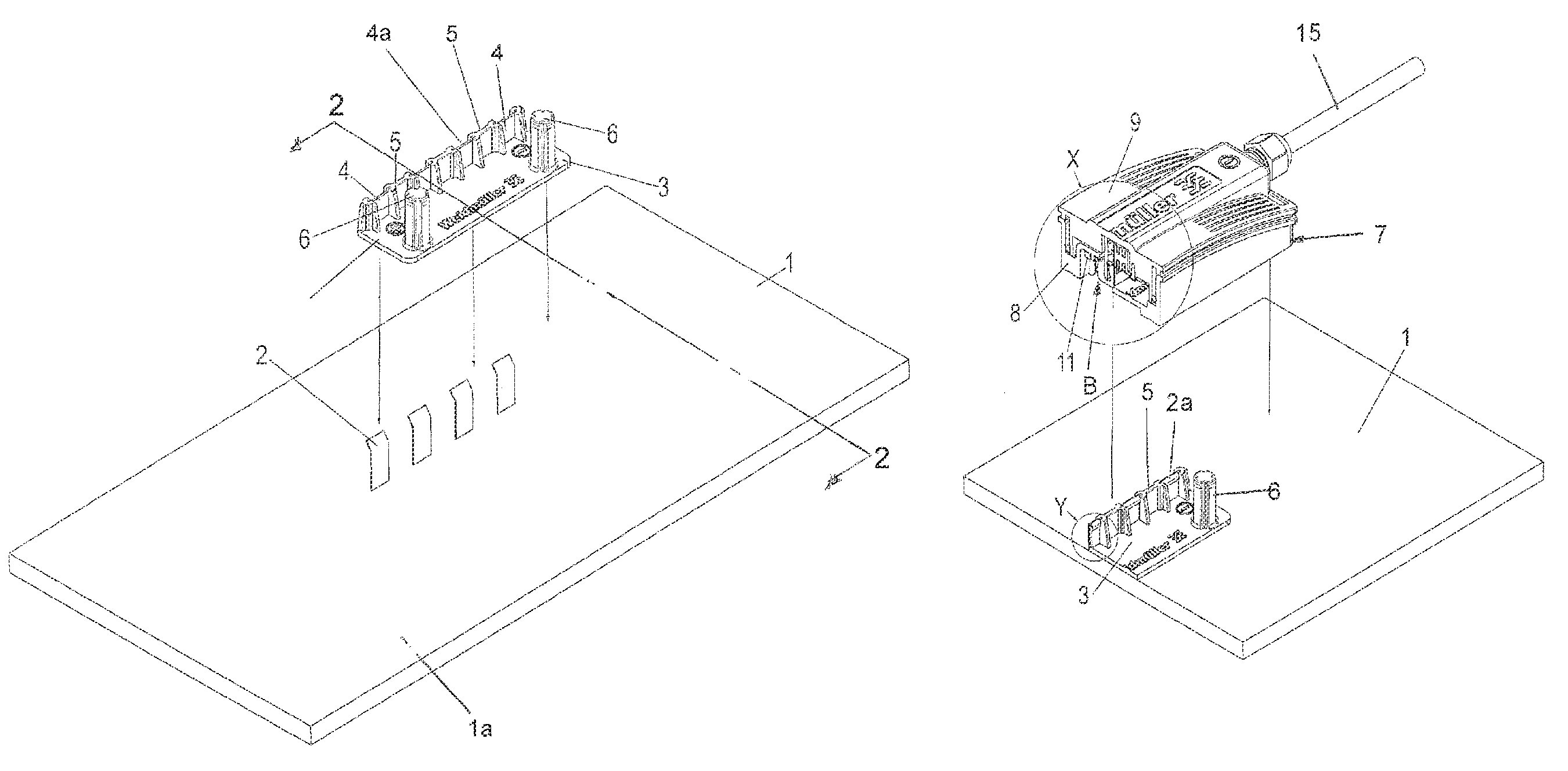
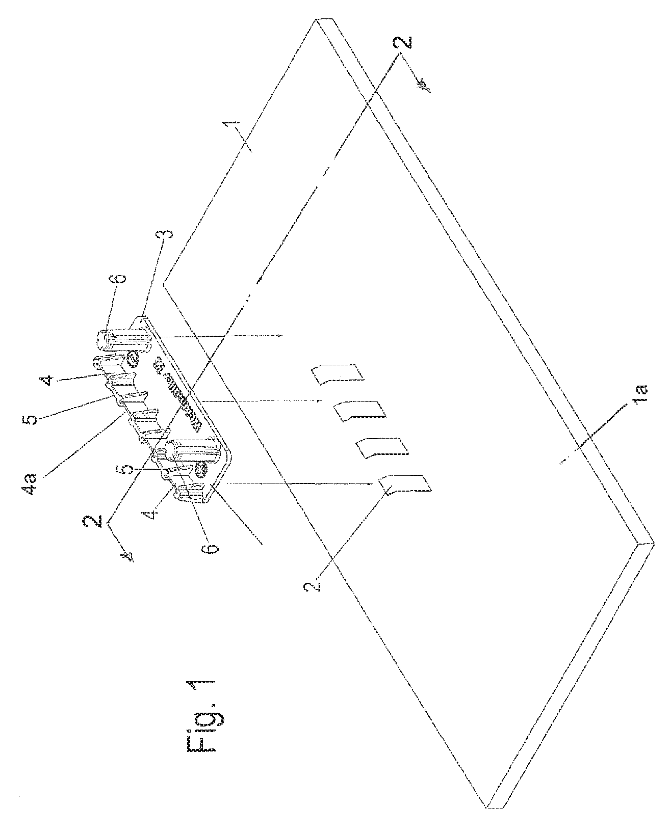
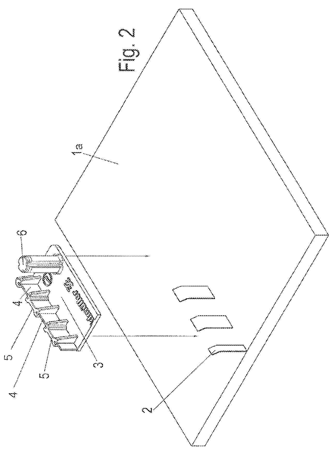
[0030]Referring first more particularly to FIGS. 1 and 2, the photovoltaic cell 1 includes a generally horizontal planar rectangular support panel 1a from which extend vertically a plurality of flat coplanar conductors 2. A flat conductor support member 3 formed from a suitable synthetic plastic electrically insulting material includes a base portion 3a that is secured to the panel upper surface, for example, by a two-side adhesive strip, adjacent the flat conductors 2. Extending upwardly from the base portion 3a are a plurality of integral bridge portions 4 having horizontal flat upper edges 4a that are separated from each other by integral separator walls 5. As best shown in FIG. 4c, the free upper ends 2a of the flat conductors 2 are reversely bent downwardly about the bridge edges 4a, respectively. A pair of integral guide pedestals 6 extend vertically upwardly from the base portion 3a of the flat conductor support member 3, which guide pedestals are adapted to extend into corre...


PUM


Abstract

A connector arrangement connects the flat conductors that extend upwardly from a horizontal photovoltaic cell panel with the insulated conductors of a cable via the circuits of a printed circuit board, respectively. A flat conductor support member is adhesively secured to the upper surface of the horizontal photovoltaic cell panel and includes upwardly extending bridge portions having flat upper edges about which are reversely bent the upper free ends of the flat conductors. A hollow sectional connector housing includes a lower body section containing a bottom opening that receives the flat conductor support member when the lower body section is seated on the panel upper surface. Bifurcated resilient contacts mounted on the lower section have first portions that engage the bent flat conductor ends, respectively, and second portions that engage the circuits on a replaceable printed circuit board carried by the removable upper cover section of the housing.

Description

BACKGROUND OF THE INVENTION[0001]1. Field of the Invention[0002]A connector arrangement connects the flat conductors that extend upwardly from a horizontal photovoltaic cell panel with the insulated conductors of a cable via the circuits of a printed circuit board, respectively. A flat conductor support member is adhesively secured to the upper surface of the horizontal photovoltaic cell panel and includes upwardly extending bridge portions having flat upper edges about which are reversely bent the upper free ends of the flat conductors. A hollow sectional connector housing includes a lower body section containing a bottom opening that receives the flat conductor support member when the lower body section is seated on the panel upper surface. Bifurcated resilient contacts mounted on the lower section have first portions that engage the bent flat conductor ends, respectively, and second portions that engage the circuits on a replaceable printed circuit board carried by the removable ...

Claims


Application Information

Patent Timeline
Patent Type & Authority Patents(United States)
IPC IPC(8): H01R9/22H01R12/00H01L25/00
CPCH01L31/02013H01R12/718H01R13/112H02S40/34H01R13/665H01R13/5213Y02E10/50
Inventor BECK, THORSTENHOLTERHOFF, KLAUSBOENSCH, MATTHIASPUESCHNER, KLAUSWUENSCHE, TORSTEN
Owner WEIDMULLER INTERFACE GMBH & CO KG
Learn More