
Wind turbine

a wind turbine and wind power technology, applied in the direction of wind turbines, electric generator control, vessel construction, etc., can solve the problems of high load on the structure of wind turbines, high cost, and high load on wind turbines

Active Publication Date: 2010-10-26
PIASECKI FREDERICK W +1
View PDF26 Cites 27 Cited by
  • Summary
  • Abstract
  • Description
  • Claims
  • Application Information

AI Technical Summary

Benefits of technology

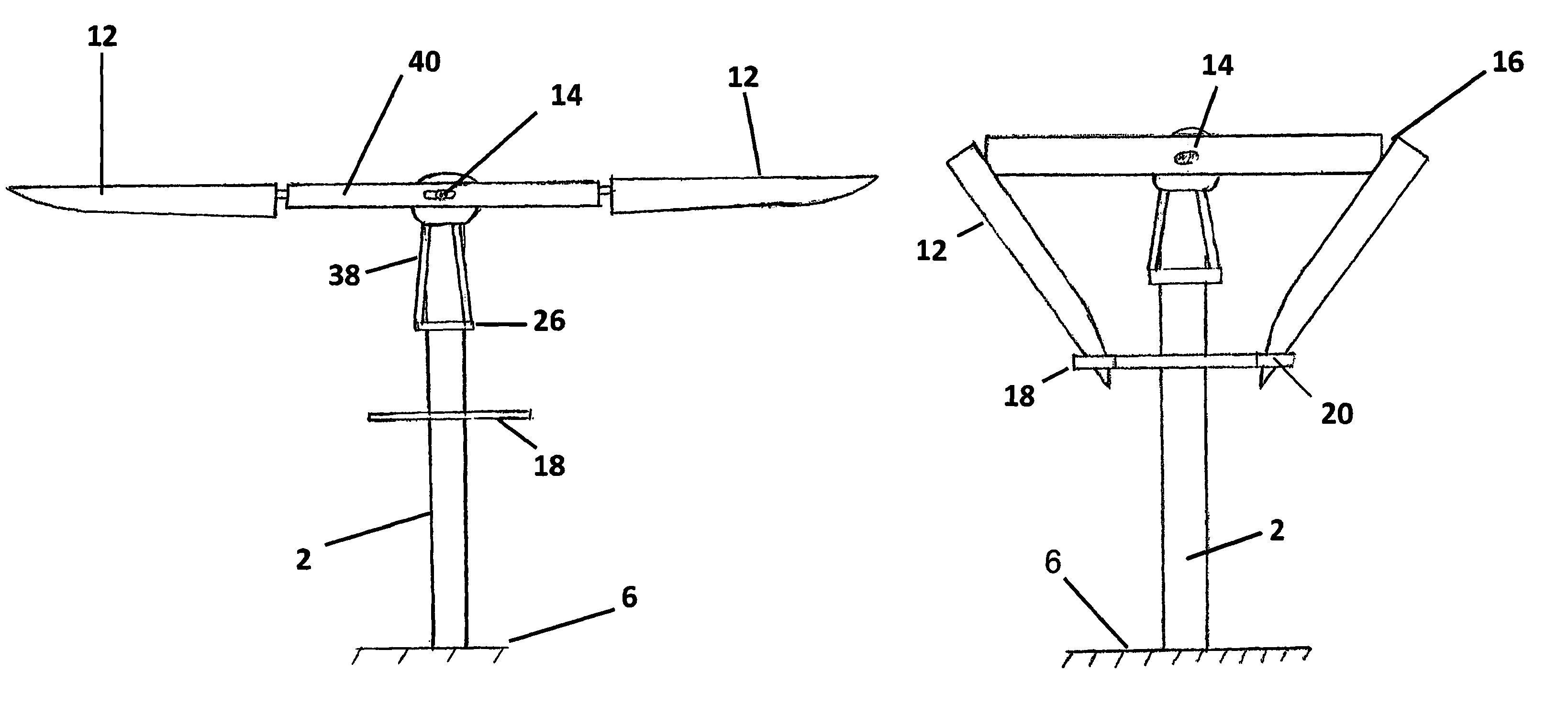
[0016]The rotor features turbine blades that fold and that may be moored to the tower during events of excess wind speed or other adverse weather conditions. Mooring the blade to the tower unloads the blade, blade root, hub and blade bearings, substantially reducing the force of the wind on those components. As a result, relatively lightweight and inexpensive hub, bearings, power transmission systems and blades may be used for a large wind turbine, substantially reducing the cost of the wind turbine and easing maintenance tasks.
[0050]Use of the second yaw bearing allows a substantial portion of the weight of the blades, hub and nacelle to be supported as an axial load by the second, or lower, yaw bearing and avoids the extreme loading of the first yaw bearing due to the leverage of an off-center load.

Problems solved by technology

Gusts, variable wind speeds and inclement weather can place a very high loading on the structures of a wind turbine.
Wind turbines also are subject to frequent starting and stopping and loads.
The problem with this approach is that the resulting turbines are inefficient at low wind speeds, bulky, heavy, expensive, difficult to build and difficult to transport.
Such large gears can be produced by very few suppliers using very expensive, custom-built equipment.
Large current-technology wind turbines cannot be easily transported by road due to the size and bulk of the components, particularly the tower and blades.
Erection of such a turbine is a significant construction project requiring use of heavy equipment and large cranes.
Current technology yaw bearing must be very large, strong, and expensive to support the resulting bending moments.
The prior art does not teach the wind turbine of the Invention.

Method used


Image

  • Wind turbine
  • Wind turbine
  • Wind turbine

Examples


Embodiment Construction

[0068]The Invention is a wind turbine electrical generator for use in low wind conditions.

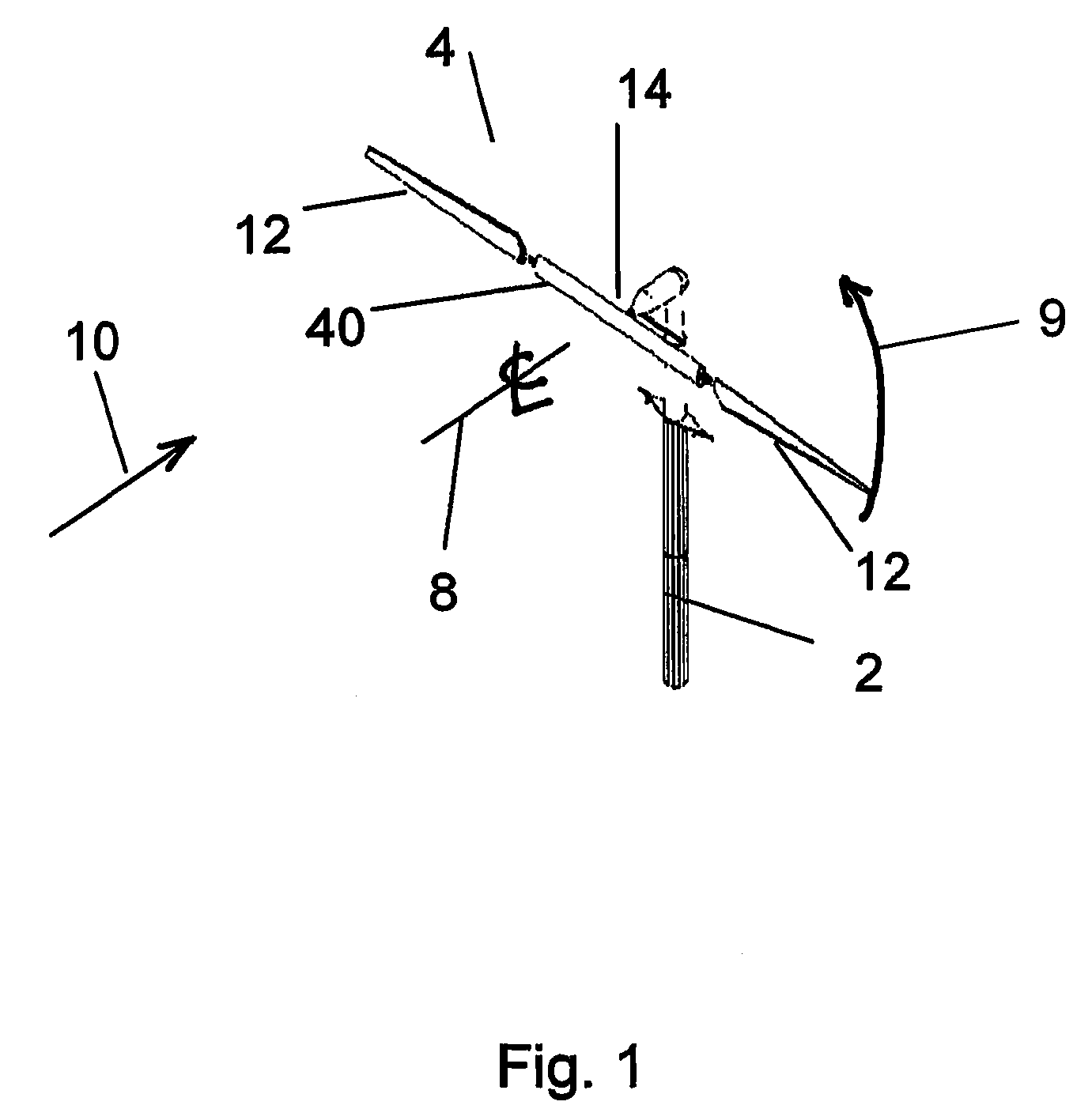
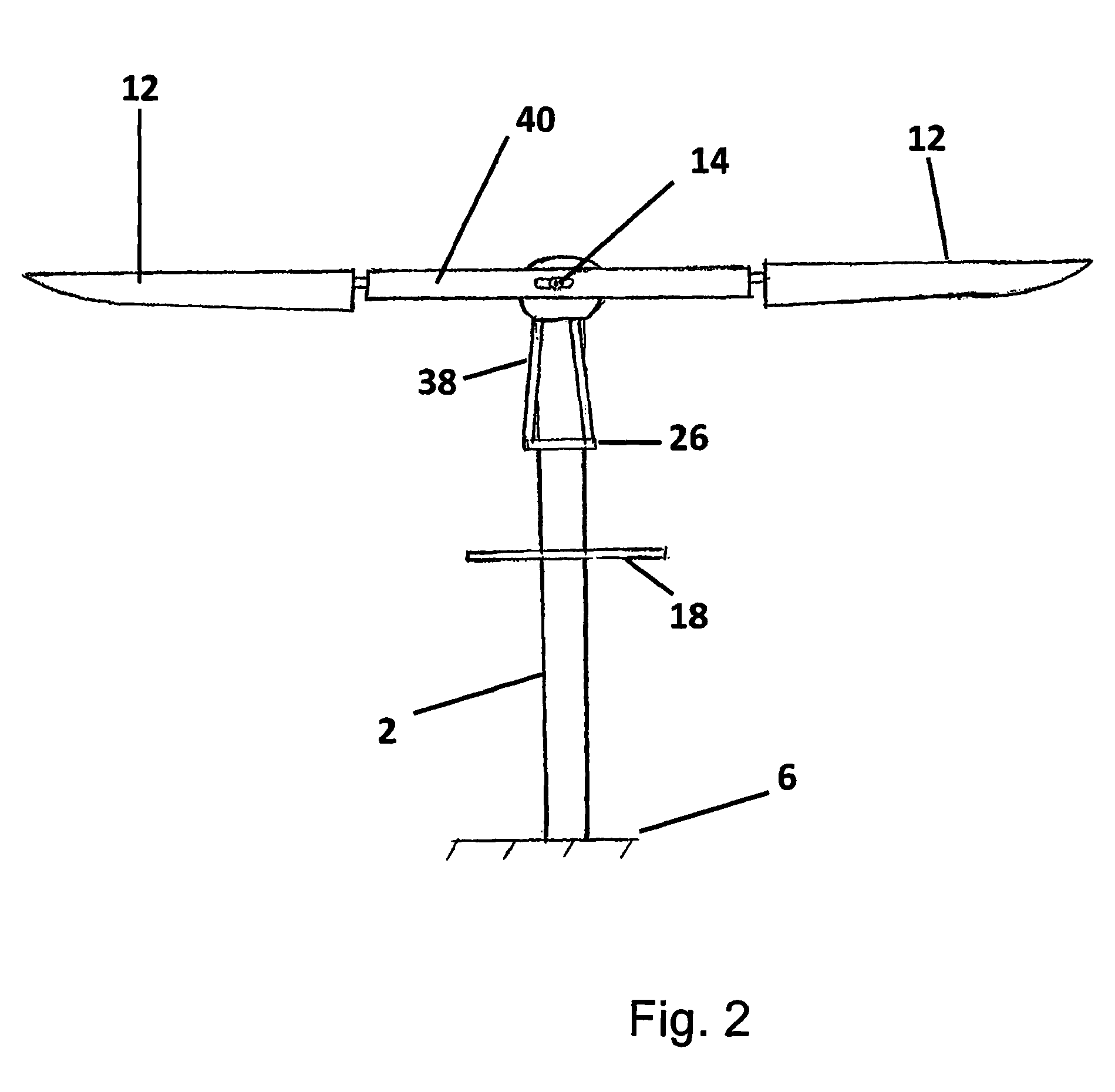
[0069]As shown by FIGS. 1-3, the wind turbine of the Invention features a tower 2 and a wind turbine rotor 4 supported by the tower 2 above the surface of a ground 6. The wind turbine rotor 4 has an axis of rotation 8 and is of the horizontal upwind type; that is, the axis of rotation 8 is generally horizontal with respect to the Earth and the wind turbine rotor 4 is located upwind of tower 2. The Invention also may be applied to horizontal downwind-type wind turbines.

[0070]The wind turbine rotor 4 includes turbine blades 12 and is configured to rotate in direction 9 in response to a wind 10. The wind turbine rotor 4 has a first position, illustrated by FIGS. 1 and 2, and a second position, illustrated by FIG. 3. In the first position, also referred to herein as the ‘deployed position,’ wind turbine blades 12 are radially arrayed about a hub 14 and configured for rotation in response to wind 10...


PUM


Abstract

A wind turbine has a horizontal axis of rotation and features a hub beam and two turbine blades attached to opposing ends of the hub beam in a spaced-apart relation. The blades have a first position in which the blades are radially arrayed about the hub beam. The blades have a second position in which the blades are folded and moored to the tower. A control system communicates with weather sensors and determines whether to move the blades between the first and second positions.

Description

BACKGROUND OF THE INVENTION[0001]1. Field of the Invention[0002]The Invention relates to wind turbines for production of electrical power. The invention is particularly applicable to wind generators that may be used in locations where high average winds are not expected but that nonetheless must survive adverse weather conditions and loadings specified by applicable building codes for wind turbines.[0003]2. Description of the Related Art[0004]The potential for wind power energy generation for a location is measured by a scale referred to as the ‘wind power class.’ There are seven ‘wind power classes,’ ranging from class 1, with annual average wind speeds of less than 5.6 meters / sec at an elevation of 100 meters, to class 7, with annual average wind speeds of 8.8 meters / sec and above at an elevation of 100 meters. Much of the United States (and the world) has relatively low average wind speeds. For example, much of the Commonwealth of Pennsylvania falls within classes 3 or 4, with an...

Claims


Application Information

Patent Timeline
Patent Type & Authority Patents(United States)
IPC IPC(8): F03D9/00H02P9/04
CPCF03D1/0658F03D7/0228F03D7/0236F03D7/0268F03D7/042F05B2240/2022F05B2240/2023Y02E10/721Y02E10/723Y02E10/72
Inventor PIASECKI, FREDERICK W.JOHNSON, DOUGLAS
Owner PIASECKI FREDERICK W
Learn More