
Implantable tissue ischemia sensor

a sensor and tissue technology, applied in the field of implantable tissue ischemia sensors, can solve the problems of insufficient oxygen delivery to meet the metabolic needs of the tissue, unreliable clinical detection of ischemia, and ischemia is especially difficult to detect, and noninvasive imaging of ischemia lacks the immediacy that allows for early intervention or real-time feedback

Inactive Publication Date: 2010-10-12
J FITNESS LLC
View PDF78 Cites 35 Cited by
  • Summary
  • Abstract
  • Description
  • Claims
  • Application Information

AI Technical Summary

Benefits of technology

This approach provides real-time feedback for immediate intervention, is safe for deployment in the body, and can be coupled with therapeutic devices, offering a direct and reliable detection of ischemia across various organs, including the heart, lungs, and gut, and can detect other conditions like tissue rejection and infection.

Problems solved by technology

The clinical detection of ischemia—an insufficient delivery of oxygen to meet a tissue's metabolic needs—is unreliable.
Ischemia is especially difficult to detect when the ischemia is due to a localized interruption of blood flow—such as during a heart attack or stroke.
Noninvasive imaging of ischemia lacks the immediacy that allows for early intervention or real-time feedback to other devices such as pacemakers.
However, such devices monitoring multiple external sites using wire leads placed upon the chest wall are not designed for implantability, which requires that issues of size, power consumption, biocompatibility, and robustness over time be optimized alongside sensing performance, a non-trivial task.
However, implantable sensors designed to detect ischemia are rare in the art, and none of these detect tissue ischemia directly.
Therefore, none of the above devices detect local tissue ischemia directly, nor can they be applied generally to any organ without regard to site.
All of the above devices are limited by being either non-implantable, by being at best an indirect measures of local tissue ischemia, or by being restricted to use in just one organ such as the heart due to the indirect measures of ischemia (such as sound or movement) which they employ.
None of the prior devices or methods allow for a direct detection of local tissue ischemia in a broad array of target sites using a long-term or short-term implantable system sensitive to local ischemia,
Such a system has not been previously described, nor successfully commercialized.

Method used


Image

  • Implantable tissue ischemia sensor
  • Implantable tissue ischemia sensor
  • Implantable tissue ischemia sensor

Examples


example

[0058]The breadth of uses of the present invention is best understood by example. This example is by no means intended to be inclusive of all uses and applications of the apparatus, merely to serve as a case study by which a person, skilled in the art, can better appreciate the methods of utilizing, and the scope of, such a device.

[0059]In this example, an optical sensor, similar in basis of operation to device 101, is implanted into abdomen of a patient undergoing colon surgery. In this case, the animal receives heart-lung bypass, such that the blood flow and oxygen content of the blood is exactly controlled by a bypass specialist rather than by the animal's own heart and lungs, affording the ability to create and resolve ischemia at will. An aortic Doppler probe is placed, which measures the delivery of blood to tissue. In this case, when the rate of the pump is lowered to zero flow, ischemia must exist in the tissues being monitored.

[0060]Analysis of the tissue ischemia is perfor...


PUM


Abstract

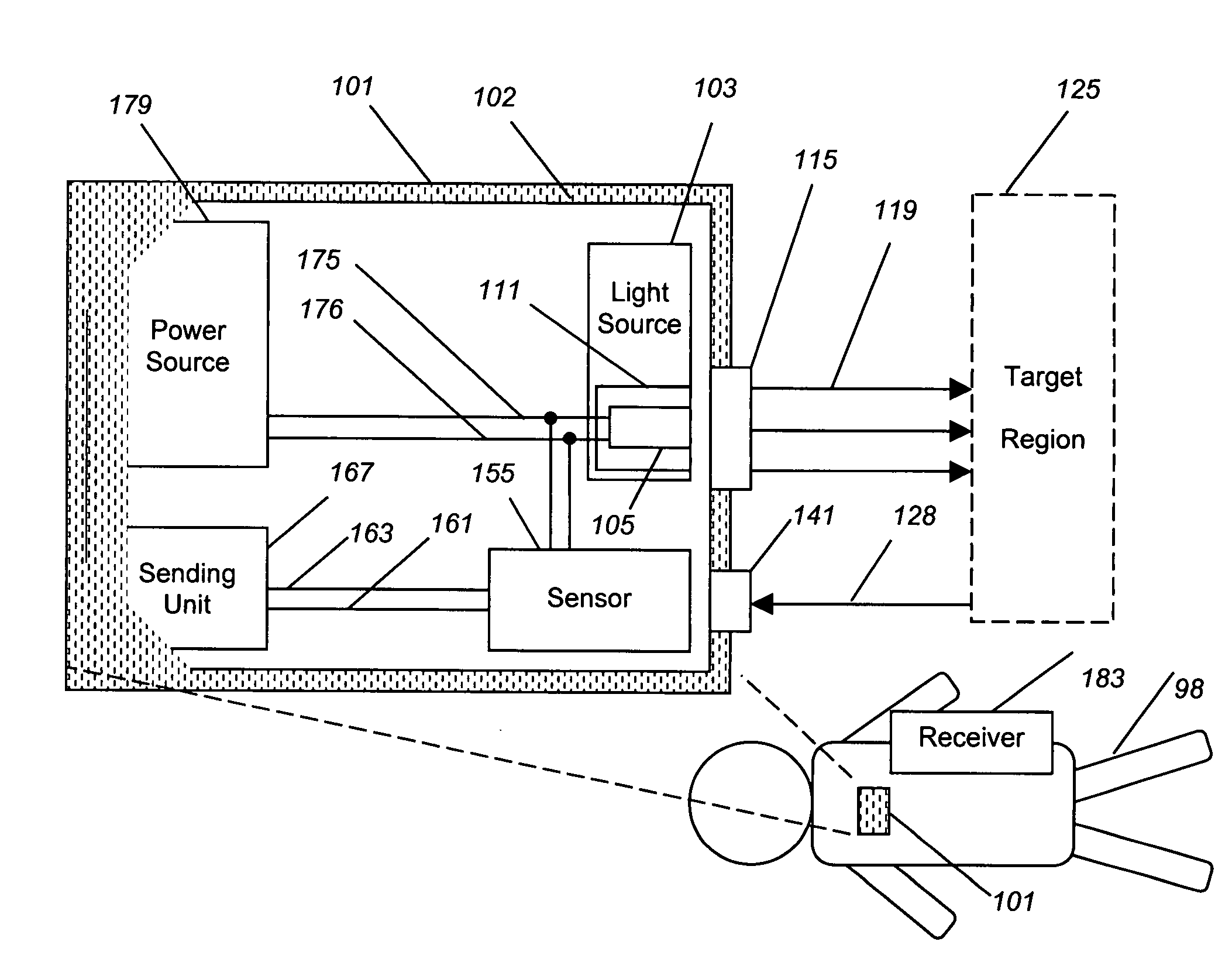
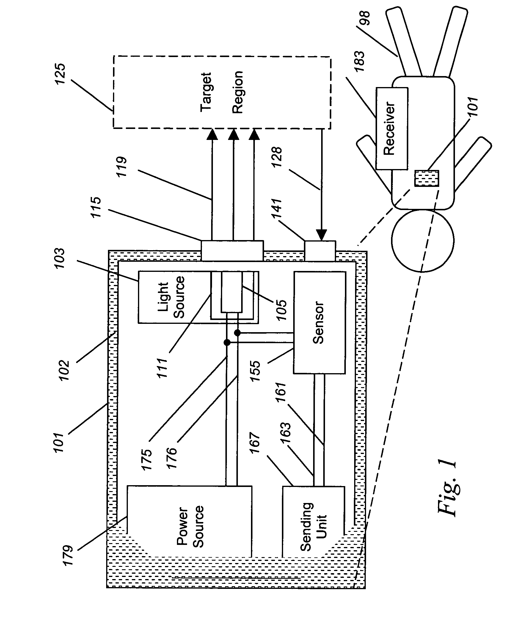
An implantable ischemia detection system in which a white LED (105) produces a continuous, visible, broadband light illuminating a target site (125). Light backscattered by the target is collected by a sensor (155), allowing for an index of ischemia to be determined, and subsequently transmitted by a sending unit (167). Power is provided by an internal power source (179). The entire implantable device is encapsulated by a biocompatible shell (102) to add long-term safety with regard to implantation.

Description

FIELD OF THE INVENTION[0001]The present invention relates to implantable devices and methods for providing localized measurements of tissue ischemia, and more particularly relates to the embedding of a visible light source, a sensor, a power source, and a transmitter into a long-term implantable shell for the purpose of performing real-time spectroscopic analysis of in vivo tissue perfusion sensitive to local tissue ischemia.BACKGROUND OF THE INVENTION[0002]The clinical detection of ischemia—an insufficient delivery of oxygen to meet a tissue's metabolic needs—is unreliable. Ischemia is especially difficult to detect when the ischemia is due to a localized interruption of blood flow—such as during a heart attack or stroke. Existing laboratory tests for ischemia, such as serum enzyme-leakage tests (e.g., for tests for cardiac isoenzymes after a heart attack) or EKG electrical tests, are insensitive indicators of such local tissue ischemia, especially during the early stages. Similarl...

Claims


Application Information

Patent Timeline
Patent Type & Authority Patents(United States)
IPC IPC(8): A61B5/00
CPCA61B5/0031A61B5/0261A61B5/14542A61B5/1459A61B5/412
Inventor BENARON, DAVID A.PARACHIKOV, ILIAN H.FIERRO, MICHAEL R.
Owner J FITNESS LLC
Learn More