
Electronic clinical thermometer and method of producing the same

a technology of electronic clinical thermometers and thermometers, which is applied in the direction of positive temperature coefficient thermometers, heat measurement, instruments, etc., can solve the problems of inability to firmly attach the lead wire to the inner wall of the sensor cap, slow rise in temperature, and longer measurement time,

Inactive Publication Date: 2010-10-05
A STUCKI CO +1
View PDF31 Cites 328 Cited by
  • Summary
  • Abstract
  • Description
  • Claims
  • Application Information

AI Technical Summary

Benefits of technology

The present invention is about a method of producing an electronic clinical thermometer with a temperature-sensitive element and lead wire. The method includes steps of mounting the sensor cap on the probe part, connecting the lead wire with the circuit board, and incorporating the circuit board into the body case. The sensor cap has a cavity with the lead wire and temperature-sensitive element inside, and the lead wire is fixed to the inner wall of the cavity. The cavity has a hemispherical or half-oval-spherical shape to hold the temperature-sensitive element and lead wire. The method may also include steps of filling the cavity with adhesive to fasten the temperature-sensitive element and lead wire. The technical effects of this invention include improved accuracy and reliability of temperature measurement, simplified production process, and reduced production costs.

Problems solved by technology

Therefore, there has been a problem that the heat on the thermistor escapes towards the non-contact lead wire, whereby a rise in temperature becomes slower and longer time is necessary for measurement.
Therefore, there is a possibility that the lead wire may be broken.
With the structure of the electronic clinical thermometer and a method of producing the same as described in the above patent document 4, it is not possible to firmly attach the lead wire onto the inner wall of the sensor cap.
Therefore, there has been a problem that a desired high-speed electronic clinical thermometer cannot be produced.

Method used


Image

  • Electronic clinical thermometer and method of producing the same
  • Electronic clinical thermometer and method of producing the same
  • Electronic clinical thermometer and method of producing the same

Examples


Embodiment Construction

[0064]Hereinafter, with reference to the accompanying drawings, an electronic clinical thermometer and a method of producing the same according to a preferred embodiment of the present invention will be explained.

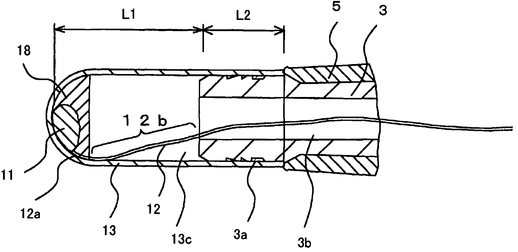
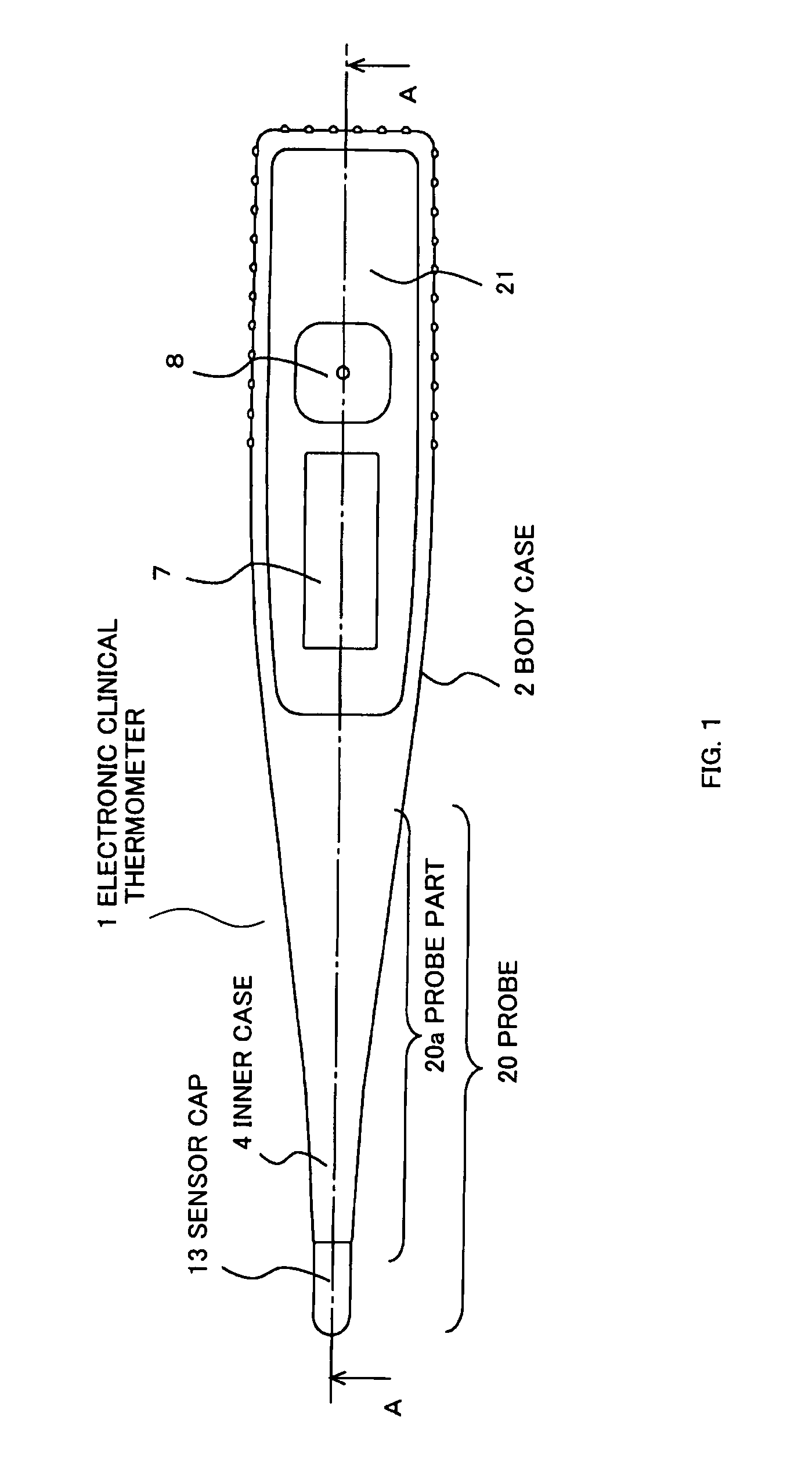
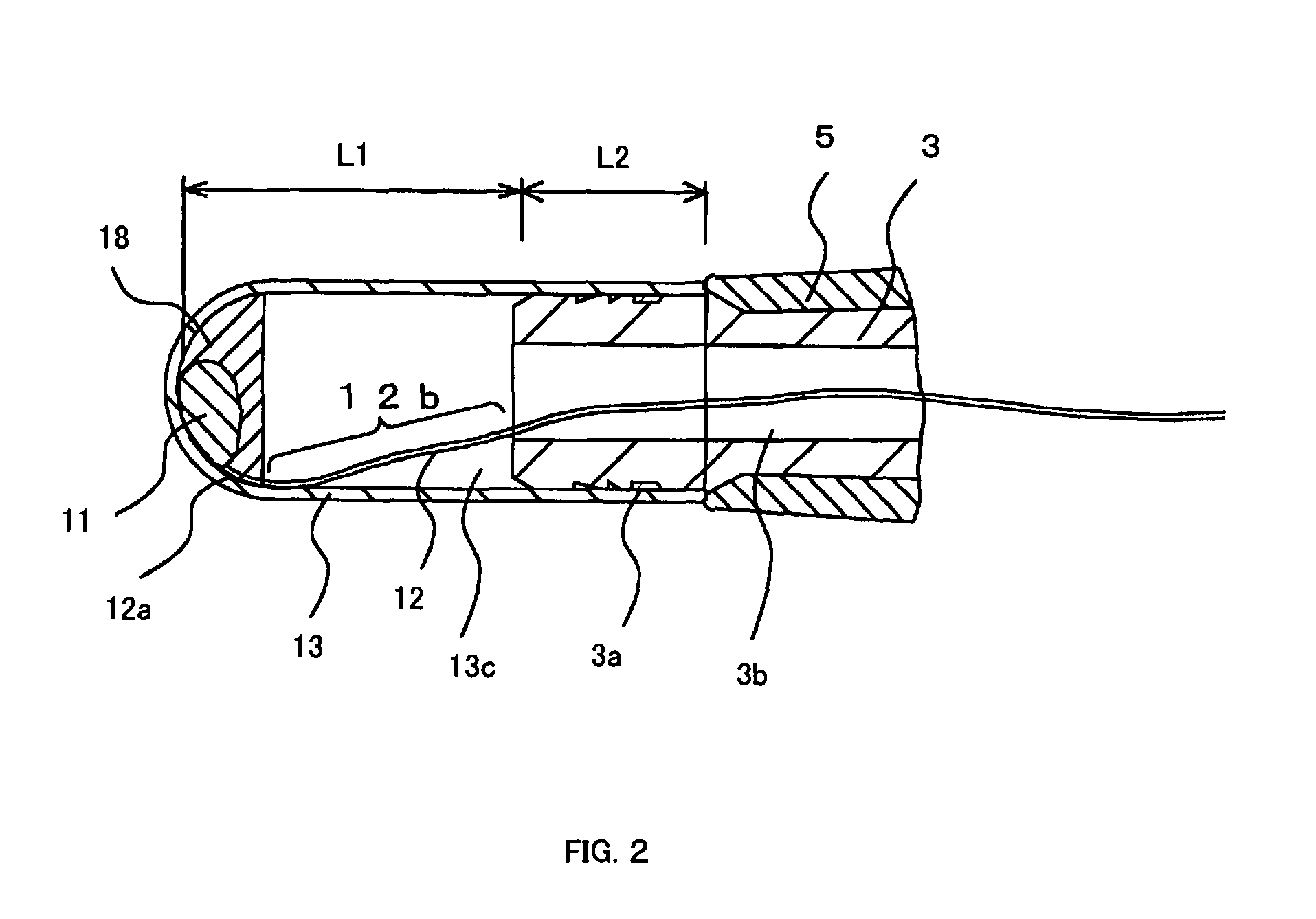
[0065]FIG. 1 to FIG. 5 relate to an embodiment of the present invention. FIG. 1 is an external view of an electronic clinical thermometer according to the present invention; FIG. 2 is a partial cross sectional view of a probe part in the electronic clinical thermometer as shown in FIG. 1; FIG. 3 is a cross sectional view of the electronic clinical thermometer taken along the line A-A of FIG. 1; FIG. 4 is a cross sectional view of a sensor cap; and FIG. 5 includes external views each showing a thermistor to which lead wire is connected.

[0066]In FIG. 1 to FIG. 3, the electronic clinical thermometer 1 according to the present embodiment includes a body case 2. This body case 2 is formed by integrally molding components according to a method and the like described below, the co...


PUM

PropertyMeasurementUnit
temperature-aaaaaaaaaa
temperatureaaaaaaaaaa
lengthaaaaaaaaaa

Abstract

A method of producing an electronic clinical thermometer is disclosed, the electronic clinical thermometer including a temperature-sensitive element, lead wire that is connected to the temperature-sensitive element, a body case having a probe part in which an insertion path for the lead wire to be inserted is formed, and a sensor cap having a cavity one end of which is opened and the other end is closed, both the lead wire projecting from the insertion path and the temperature-sensitive element being stored within the sensor cap, and the method includes a step for mounting the sensor cap on the probe part, in a state where the lead wire having the temperature-sensitive element mounted on the tip thereof projects from the insertion path of the probe part.

Description

FIELD OF THE INVENTION[0001]The present invention relates to an electronic clinical thermometer and a method of producing the same.BACKGROUND OF ART[0002]An electronic clinical thermometer, wide-spreading currently, includes a button type battery as a power source and a probe that is brought into contact with axillar or a part under the tongue, so as to detect a change in resistance of temperature-sensitive element (thermistor) placed in the probe, convert the detected value into a temperature value, and display the temperature on a liquid crystal display (LCD), and this type of electronic clinical thermometer is commonly used. This type of electronic clinical thermometer incorporates in a plastic case, a power source battery, a measurement circuit, an LCD, an operating switch, and the like. The probe is formed on one end of the electronic clinical thermometer body, and the probe includes a probe body in which an insertion path for inserting a lead wire connected to the thermistor, ...

Claims


Application Information

Patent Timeline
Patent Type & Authority Patents(United States)
IPC IPC(8): G01K1/00
CPCG01K1/083G01K13/002Y10T29/49085G01K13/25G01K13/20
Inventor KOBAYASHI, ISAMU
Owner A STUCKI CO
Learn More