
Compact broadhead

a broadhead and compact technology, applied in the field of broadheads, can solve the problems of affecting accuracy, unable to heat carbon arrows, and the broadheads have always been difficult to tune, so as to reduce the length of the broadhead, facilitate penetration of the tip, and compact length

Active Publication Date: 2010-09-28
SULLIVAN KEVIN MICHAEL
View PDF7 Cites 4 Cited by
  • Summary
  • Abstract
  • Description
  • Claims
  • Application Information

AI Technical Summary

Benefits of technology

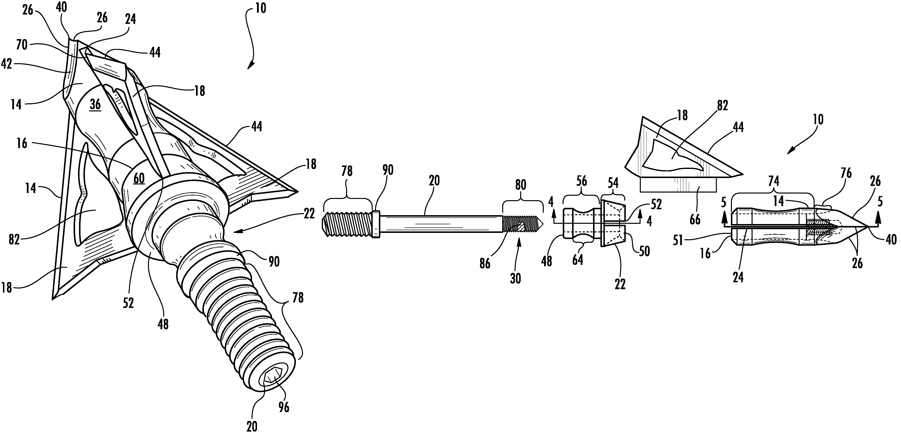
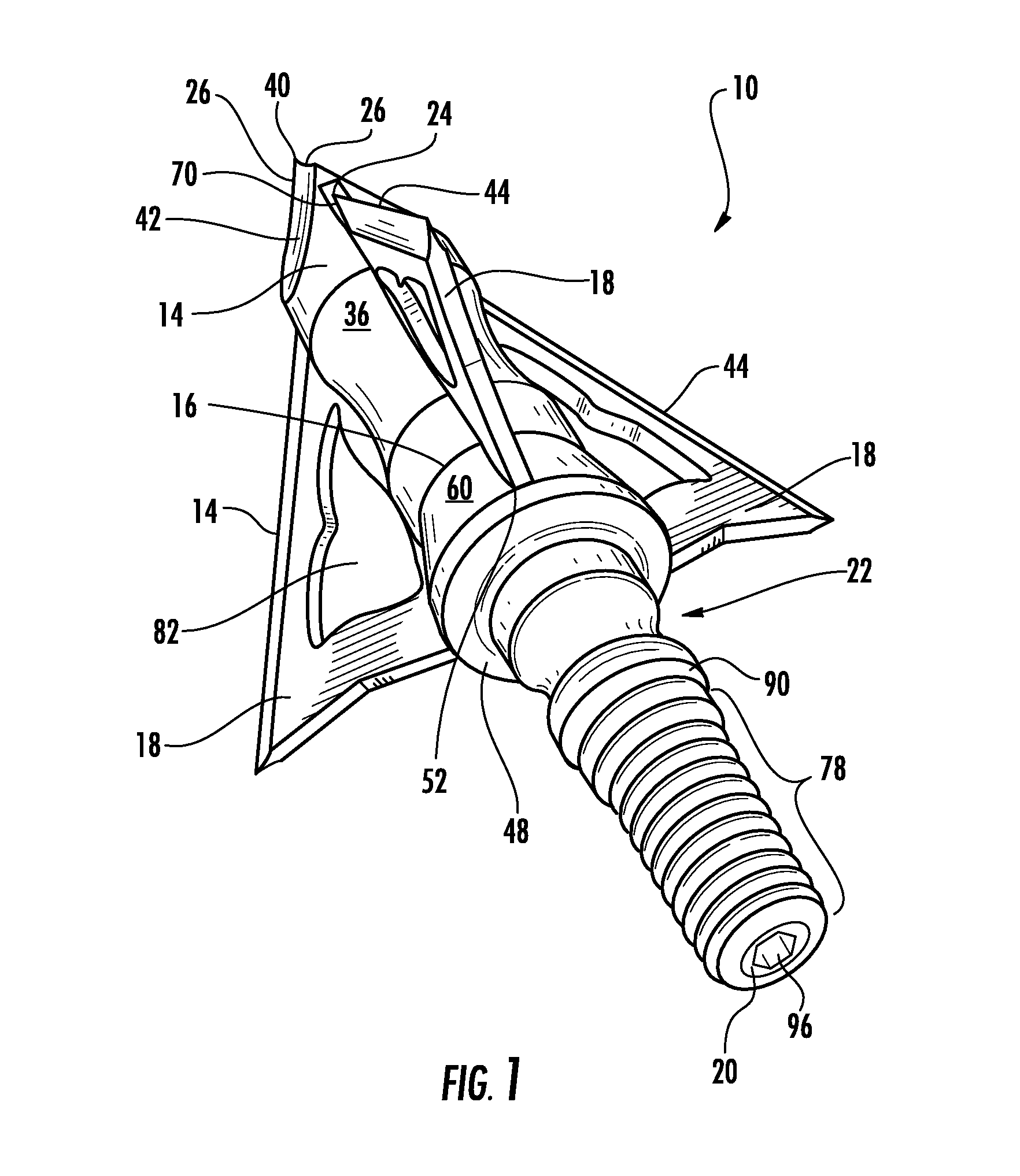
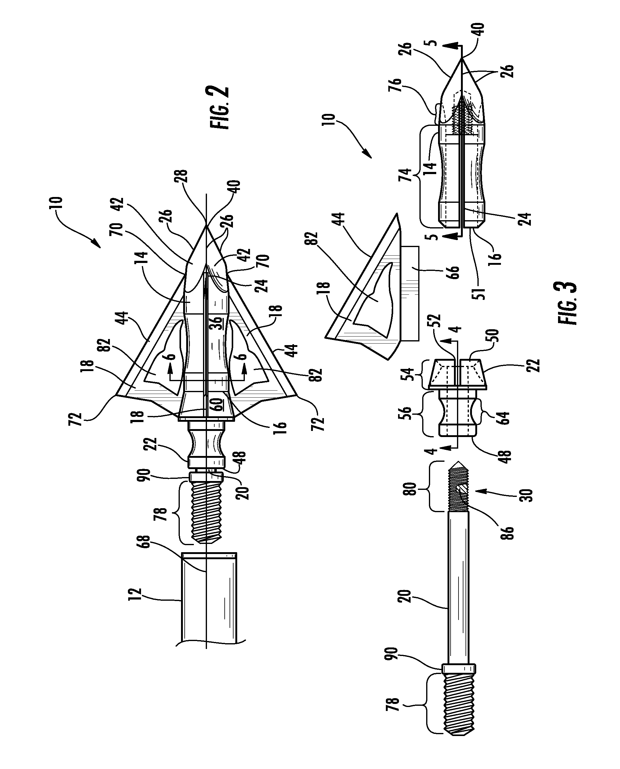
[0006]This invention relates to a compact broadhead attachable to an arrow shaft. The broadhead is constructed such that the broadhead is relatively compact in length in comparison to conventional broadheads. The broadhead may be formed from a tip configured to facilitate penetration of the tip into an object. The tip may include an open proximal end into which blades and an elongated engaging bar are inserted. The blades extend outwardly through slots in the tip and are held in place with the elongated engaging bar forcing a base against the tip. The blades may be aligned with cutting arrises on the tip, which enables the blades to be positioned closer to the distal end of the tip, thereby reducing the length of the broadhead. The broadhead may also include a tunable broadhead system enabling orientation of the blades of the broadhead to be changed relative to an arrow.
[0011]An advantage of this invention is that the blades may be positioned closer to the distal end of the tip than conventional broadheads because the blade slots are aligned with the cutting arrises at the distal end of the tip, thereby creating a compact broadhead with replaceable blades.
[0012]Another advantage of this invention is that the blades may be oriented in any position independent of the orientation of the insert within an end of the arrow shaft. Thus, the blades may be oriented in any positioned about a longitudinal axis of the arrow shaft to improve clearance and accuracy. For instance, the blades of three blade embodiments may be aligned with the fletching on the arrow. In other embodiments, such as two blade embodiments, the blades may be aligned to reduce planing upon the broadhead leaving the bow during the initial moments of the shot.

Problems solved by technology

Broadheads have always proved challenging to tune.
Otherwise, the blades can act as airfoils and cause the arrows to plane, which severely affects accuracy.
Carbon arrows may not be heated because the heat can easily damage the carbon fibers.
While heating the arrows enables the inserts to be rotatable within the arrow shaft, repeated heating typically reduces the strength of the glues and often creates poor connections between the inserts and the arrows.

Method used


Image

  • Compact broadhead
  • Compact broadhead
  • Compact broadhead

Examples


Embodiment Construction

[0023]As shown in FIGS. 1-8, this invention is directed to a compact broadhead 10 attachable to an arrow shaft 12. The broadhead 10 is constructed such that the broadhead 10 is relatively compact in length in comparison to conventional broadheads. The broadhead 10 may be formed from a tip 14 configured to facilitate penetration of the tip 14 into an object. The tip 14 may include an open proximal end 16 into which blades 18 and an elongated engaging bar 20 are inserted. The blades18 extend outwardly through slots 24 in the tip 14 and are held in place with the elongated engaging bar forcing a base 22 against the tip 14. The blades 18 may be aligned with cutting arrises 26 on the tip 14, which enables the blades 18 to be positioned closer to the distal end 28 of the tip 14, reducing the length of the broadhead 10. The broadhead 10 may also include a tunable broadhead system 30 enabling orientation of the blades 18 of the broadhead 10 to be changed relative to an arrow 12.

[0024]The ti...


PUM


Abstract

An axially compact broadhead for archery and other such purposes is disclosed. The broadhead may be formed from a tip configured to facilitate penetration of the tip into an object with a pointed distal end and an opposite proximal end. The tip may include a central tip chamber extending distally into the tip from the proximal end and a plurality of blade slots extending from the proximal end of the tip toward the distal end. A base may be positioned proximally of the tip and have a central base chamber. One or more blades may be positioned in the blade slots and extend outwardly from the tip. An elongated engaging bar may extend through the central base chamber of the base and into the central tip chamber to affix the blades and provide a post for attaching the broadhead to an insert of an arrow.

Description

FIELD OF THE INVENTION[0001]This invention is directed generally to broadheads, and more particularly to compact broadheads.BACKGROUND[0002]Modern broadheads are tips attachable to a distal end of an arrow shaft and include one or more blades having cutting arrises. The blades extend outwardly from a generally cylindrical broadhead body. The blades typically extend from the broadhead such that the cutting arris of each blade are at an acute angle relative to a longitudinal axis of the broadhead body and extend from a distal point at an intersection at an outer surface of the broadhead body to near the tip at an outer surface of the broadhead body to a proximal point radially outward of the outer surface of the broadhead body. In this position, the blades are capable of cutting flesh as the broadhead passes through an animal.[0003]Modern compound bows can propel arrows at speeds of greater than 300 feet per second. Accurate arrow flight at such speeds is typically only accomplished w...

Claims


Application Information

Patent Timeline
Patent Type & Authority Patents(United States)
IPC IPC(8): F42B6/08
CPCF42B6/08
Inventor SULLIVAN, KEVIN MICHAEL
Owner SULLIVAN KEVIN MICHAEL
Learn More