
Cable reel mechanism

a technology of a cable and a sleeve, which is applied in the direction of flexible lead accommodation and computer periphery connectors, etc., can solve the problems of inconvenient use and inability to quickly adjust the cable, and achieve the effect of convenient operation and convenient us

Inactive Publication Date: 2010-08-31
LIAO SHENG HSIN
View PDF6 Cites 40 Cited by
  • Summary
  • Abstract
  • Description
  • Claims
  • Application Information

AI Technical Summary

Benefits of technology

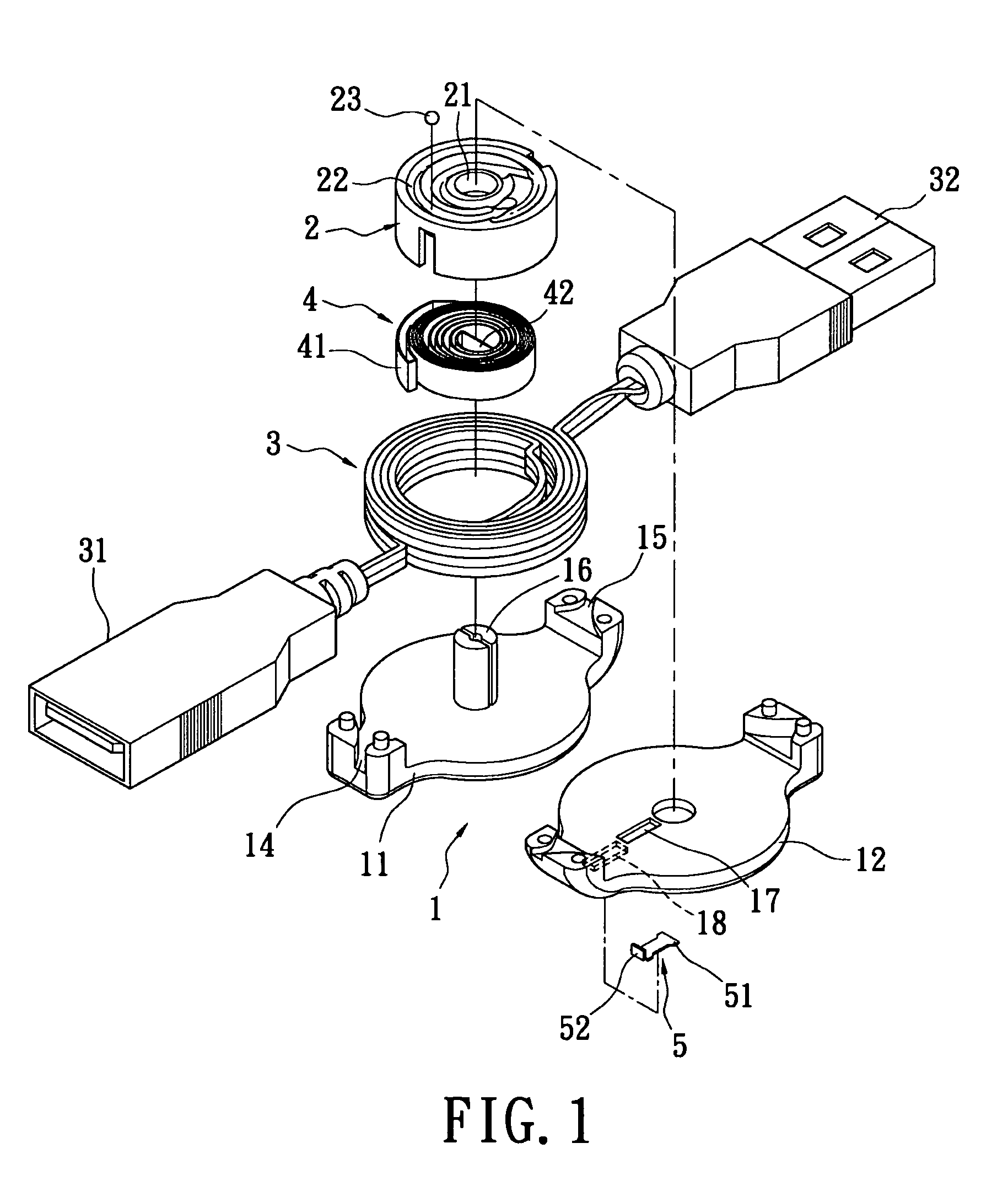
"The present invention is a cable reel mechanism that can be switched to different operation modes to make it easier and more convenient for users to pull and retract the cable to adjust its length. The mechanism includes a main body, a cable reel, a volute spring, and a switching element. The switching element can be detached from the ball bearing to allow for free rotation of the cable reel. The mechanism can be switched to three different modes by the switching element. The blocking portion of the switching element can be fastened on the stopping portion of the cable reel to fix the cable and allow for optimal operation mode selection based on different applications."

Problems solved by technology

The conventional cable reel mechanisms described above only have a single operation mode, that is, when the length of cables needs to be adjusted, it can only be achieved via repeatedly pulling then retracting which is very difficult for operation, furthermore the length of cables cannot be adjusted rapidly and directly, which causes inconvenient in use.

Method used


Image

  • Cable reel mechanism
  • Cable reel mechanism
  • Cable reel mechanism

Examples


first embodiment

[0031]Please refer to FIGS. 1-4 illustrating a cable reel mechanism according to the present invention. The cable reel mechanism at least includes a main body 1, a cable reel 2, a cable 3, a volute spring 4, and a switching element 5. The main body 1 includes a first shell 11 and a second shell 12 which may be combined together to form one part, wherein the one part is the main body 1 that is hollow, furthermore the combining of the first shell 11 and the second shell 12 is via tightening screws or fastening. The main body 1 has a receiving room 13 defined therein for receiving the cable reel 2, the cable 3, and the volute spring 4. The main body 1 further has a first cable hole 14 and a second cable hole 15 formed at the side edges thereof, and two ends of the cable 3 may extend through the first cable hole 14 and the second cable hole 15. A protruding shaft 16 is disposed on an inner wall of the main body 1 and extends into the receiving room 13. A limiting groove 17, which is a s...

second embodiment

[0039]Alternatively, as shown in FIG. 5, which shows a second embodiment according to the present invention, the sliding groove 18 has an assembly design, that is, the sliding groove 18 is formed in a seat body 19 which is fastened and mounted in a corresponding concave groove 110 of the main body 1 for convenient disassembly and assembling of the switching element 5.

third embodiment

[0040]Alternatively, as shown in FIG. 6, which shows a third embodiment according to the present invention, the switching element 5 may be pushed to move along a transverse straight line for controlling the pressing portion 51 of the switching element 5 to press the ball bearing 23 or be detached from the ball bearing 23.


PUM


Abstract

A cable reel mechanism includes a main body, a cable reel, a cable, a volute spring and a switching element. The main body has a receiving room defined therein and a limiting groove. The cable reel is turnably disposed in the receiving room of the main body and has a track groove in which a ball bearing is disposed. One portion of the ball bearing engages with the limiting groove of the main body. The cable is reeled on the cable reel. The switching element is disposed on the main body and has a pressing portion which detachably presses the ball bearing. The cable reel mechanism can be switched to different operation modes via the switching element, so that users can pull then retract the cable rapidly and directly to adjust the length of the cable, therefore the operation is easier and more convenient.

Description

BACKGROUND OF THE INVENTION[0001]1. Field of the Invention[0002]The present invention relates to a cable reel mechanism, and more particularly to a cable reel mechanism which can be switched to different operation modes according to demands.[0003]2. Description of Related Art[0004]At present, communication devices, such as computers, modems, telephones, facsimile machines and so on must be connected via proper cables to achieve communication. In order to prevent the cables being too long or too short, various cable reel mechanisms for various communication devices has been developed. Generally, most of the cable reel mechanisms each include a main body, a cable, a cable reel, and a volute spring, so that plugs of the cables can be inserted in sockets of related communication devices, thereby communicating downloaded information and adjusting the length of the cables according to actual demands.[0005]Additionally, the cable reel of each cable reel mechanism further has a track groove...

Claims


Application Information

Patent Timeline
Patent Type & Authority Patents(United States)
IPC IPC(8): B65H75/48
CPCB65H75/4431B65H75/4434H01R13/72B65H2701/34H01R2201/06
Inventor LIAO, SHENG-HSIN
Owner LIAO SHENG HSIN
Learn More