Circuit autorouter with object oriented constraints

a circuit and object-oriented technology, applied in the field of physical layout tools, can solve the problems of additional design constraints, length of routing segments, and length of routing segments, and achieve the effect of reducing the cost of routing, and reducing the number of circuit layouts

Active Publication Date: 2010-07-20
CADENCE DESIGN SYST INC
View PDF15 Cites 21 Cited by
  • Summary
  • Abstract
  • Description
  • Claims
  • Application Information

AI Technical Summary

Benefits of technology

[0046]FIGS. 28A-28E illustrate exemplary routing operation of the detail geometric routing engine on a simple circuit.

Problems solved by technology

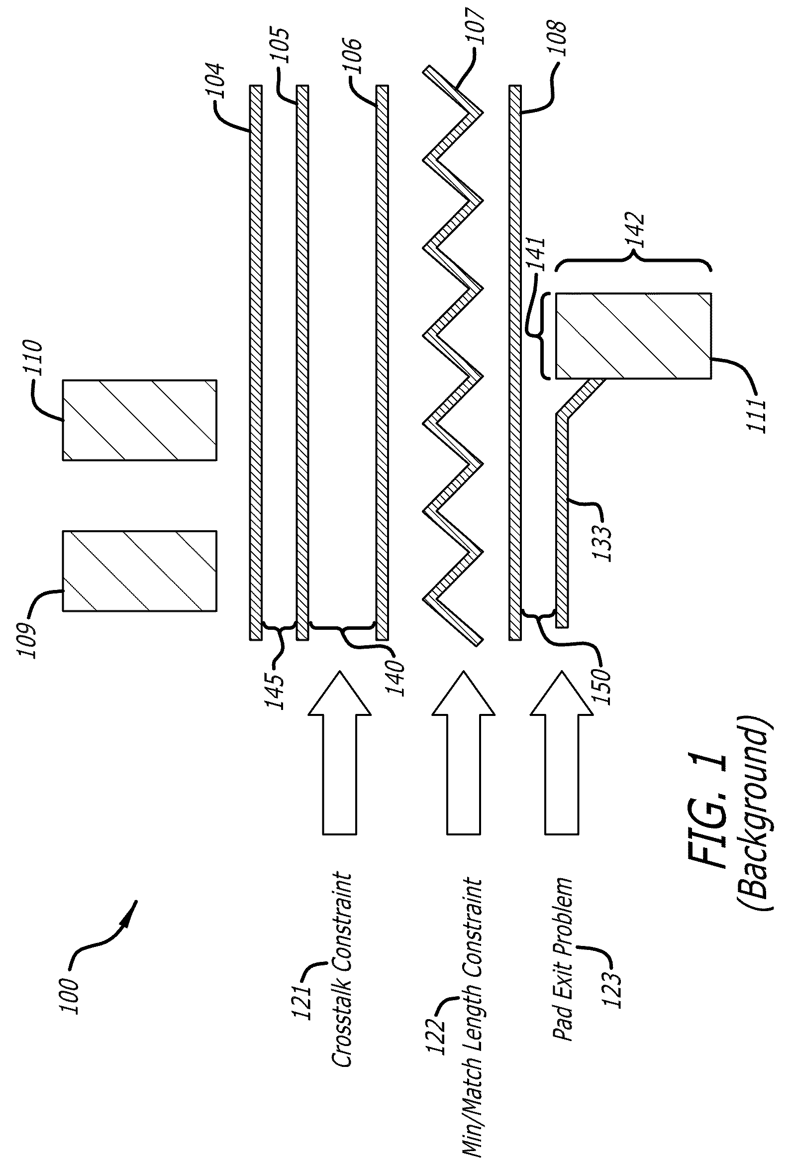
In this environment, the “cost” was the length of the routing segments.
As clock speeds increased, timing constraints were introduced such as “maximum delay” constraints.
As clock frequencies continued to increase further still, additional design constraints were added to routing a circuit layout.
However, using these two approaches to meet additional design constraints for routing a circuit design are reaching their limits and can no longer be extended.
For example, in today's high-end printed circuit board designs it may be impossible to route the constrained nets first because almost every net now has a design constraint to meet.
In fact, many nets have multiple design constraints to meet.
The multiple design constraints when attempting to route a net may interact and make it difficult, if not impossible, to further tune the cost functions as the different constraints for a net cannot be expressed as a single numeric value.
Furthermore with numerous constraints for routing a design, it is common for the constraints to conflict.
It is difficult, if not impossible, to concurrently satisfy all of these constraints when routing.

Method used


Image

  • Circuit autorouter with object oriented constraints
  • Circuit autorouter with object oriented constraints
  • Circuit autorouter with object oriented constraints

Examples


Embodiment Construction

[0051]In the following detailed description of the embodiments of the invention, numerous specific details are set forth in order to provide a thorough understanding of the present invention. However, it will be obvious to one skilled in the art that the embodiments of the invention may be practiced without these specific details. In other instances well known methods, procedures, components, and circuits have not been described in detail so as not to unnecessarily obscure aspects of the embodiments of the invention.

[0052]The embodiments of the invention include methods, apparatus and systems for an object oriented circuit autorouter having object oriented constraints.

[0053]In one embodiment of the invention, an object oriented autorouter is provided for routing nets in a circuit. The object oriented autorouter includes a routing data model (RDM), a detail geometric routing engine coupled to the routing data model, and a command and control module (CCM) coupled to the detail geometr...


PUM


Abstract

In one embodiment of the invention, an object oriented autorouter is disclosed for routing nets in a circuit. The object oriented autorouter includes a routing data model (RDM); at least one routing engine, such as a single connection router (SCR), a topographical (TOPO) transformation engine, and a detail geometric (DETAIL) engine, and a command and control module (CCM) coupled together. The RDM reads and write data with a design database as well as reading one or more object oriented design constraints. Each of the routing engines have at least one action to operate on the design database to improve compliance of the circuit to a constraint. The CCM controls the overall routing process of the nets in the circuit and includes at least one director to invoke at least one of the routing engines to achieve compliance with one or more constraints.

Description

FIELD[0001]The embodiments of the invention relate generally to physical layout tools for printed circuit boards and integrated circuits. More particularly, the embodiments of the invention relate to placement and routing tools for printed circuit boards and integrated circuits.BACKGROUND[0002]An autorouter is a collection of algorithms that attempt to find a set of wire segments (line segments on a routing layer, also referred to as “nets”) and a set of vias (connections between routing layers) that connect terminals (component pins) while at the same time satisfying a set of known design constraints, such as design rules. To do so, they make an enormous number of tiny decisions. Typically these decisions made by the algorithms in a typical autorouter are based on numerically computed “costs”. That is when faced with alternate choices, the algorithms select the lower cost alternative.[0003]Early in the history of the electronic design automation (EDA) industry, circuit designs had ...

Claims


Application Information

Patent Timeline
Patent Type & Authority Patents(United States)
IPC IPC(8): G06F17/50
CPCG06F17/5077G06F30/394
Inventor WADLAND, KENBERGAN, SEANGRANT, CHARLES W.KINGSBURY, GLENDINELAWSON, RANDALLRADUMILO-FRANKLIN, JELENAREDDY, KOTA SUJANRUSSO, STEVESCHILP, WILLIAMTSAI, DAVISWOODWARD, KEITHWOODWARD, RICHARDWU, JIA
Owner CADENCE DESIGN SYST INC
Why Eureka
Try Eureka