Device and method for controlling an electric power converter

a technology of electric power converter and control device, which is applied in the direction of electric variable regulation, process and machine control, instruments, etc., can solve the problems of large common mode voltage and current on output from the converter, high manufacturing cost, and bulky product dimensions and converter power and efficiency losses

Inactive Publication Date: 2010-07-20
SCHNEIDER ELECTRIC IND SAS
View PDF3 Cites 10 Cited by
  • Summary
  • Abstract
  • Description
  • Claims
  • Application Information

AI Technical Summary

Problems solved by technology

Voltage variations on three voltage levels with regulation according to a three-dimensional vector space operating by numerous voltage variations per regulation cycle cause very large common mode voltages and currents on output from the converter.
The use of common mode filters leads to high manufacturing costs, bulky product dimensions and converter power and efficiency losses.

Method used


Image

  • Device and method for controlling an electric power converter
  • Device and method for controlling an electric power converter
  • Device and method for controlling an electric power converter

Examples


Embodiment Construction

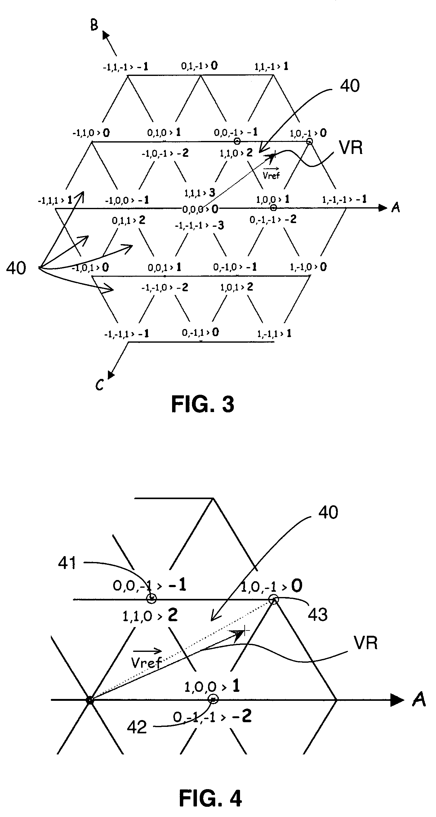
[0044]In an electric power converter control device, the converter arms are controlled according to a regulation mode defined in a vector space. FIG. 3 represents a diagram of a vector space able to determine control of the arms of a three-arm converter referenced on axes A, B and C. In this case, a reference vector VR, which is the image of the control voltages to be applied to the three arms, points in a triangle 40 of the vector space. A detail of a regulation triangle 40 of a vector space diagram is represented in FIG. 4. Apexes 41, 42 and 43 of the triangle 40 correspond to states of the power semi-conductors or to voltage states of the converter outputs during a regulation cycle. The notation of the apexes corresponds to the individual states of each output and to a global state of the outputs corresponding to the common mode voltage in reduced unit generated by the converter. Thus, during a regulation cycle equivalent to a chopping period, the outputs of the converter arms su...


PUM


Abstract

The control device of an electric power converter comprises a control circuit controlling turn-on of power semi-conductor arms. The control circuit comprises a module for determining possible turn-offs of an arm, and a module for selecting turn-offs enabling double switching from among the possible turn-offs. Selection of turn-offs enabling an arm of said converter to be turned off according to the turn-offs enabling double switching in other arms. The electric converter comprises one such control device. The method comprises determination of turn-offs enabling double switching from among the possible turn-offs, and selection of turn-offs to turn an arm of said converter off according to the turn-offs enabling double switching.

Description

BACKGROUND OF THE INVENTION[0001]The invention relates to a control device of an electric power converter. The control device may include a control means for controlling turn-on or switching voltage in one or more power semi-conductor arms.[0002]The electric power converter includes a DC power supply which includes a first positive voltage line, a second negative voltage line, and a third intermediate voltage line, and conversion means having at least three power semi-conductor arms connected between the positive, negative, and intermediate voltage lines, and outputs to supply at least one output voltage. The control means include a processing means to supply modulation signals of control signals of the arms.[0003]The invention also relates to an electric converter comprising one such control device.[0004]The invention also relates to a method for controlling one such converter.STATE OF THE ART[0005]Known converter control devices control power semi-conductor switching arms to suppl...

Claims


Application Information

Patent Timeline
Patent Type & Authority Patents(United States)
IPC IPC(8): H02M5/42H02M7/44H02M3/24H02M7/68
CPCH02M1/12H02M1/44H02M7/487H02M7/4833
Inventor BAUDESSON, PHILIPPEVIDET, ARNAUDLEMOIGNE, PHILIPPEIDIR, NADIR
Owner SCHNEIDER ELECTRIC IND SAS
Why Eureka
Try Eureka