
Return lever member, feed device, recording apparatus, and liquid ejecting apparatus

a technology of reversing levers and levers, which is applied in the direction of thin material processing, article separation, printing, etc., can solve the problems of dimensional control difficulty, significant increase in costs, and distortion

Active Publication Date: 2010-07-06
SEIKO EPSON CORP
View PDF7 Cites 8 Cited by
  • Summary
  • Abstract
  • Description
  • Claims
  • Application Information

AI Technical Summary

Benefits of technology

The invention provides a feed device for a recording apparatus that includes a return lever member. The return lever member is designed to push back a recording medium that has entered the feed path upstream of the feed path. This prevents the recording medium from causing issues in the feeding process. The feed device also includes a lever unit that can be moved to different positions to push back the recording medium and prevent it from entering the feed path. The lever unit includes a return operative portion that can push the recording medium upward, a crook portion that extends above the end support portion, and a stepped section that bends towards the end support portion. These features allow for reliable and effective prevention of recording media from entering the feed path.

Problems solved by technology

This may cause difficulty in dimensional control.
In addition, the long length of the return lever member 503 in the main scanning direction X may significantly increase costs and may create distortion thereof caused by twisting.
In this case, however, it is difficult to provide the lever units 507 to the full range in the main scanning direction X in the feed path 504.
That is, there is the possibility of being unable to reliably push back the sheet 506 unnecessarily entering the feed path 504.

Method used


Image

  • Return lever member, feed device, recording apparatus, and liquid ejecting apparatus
  • Return lever member, feed device, recording apparatus, and liquid ejecting apparatus
  • Return lever member, feed device, recording apparatus, and liquid ejecting apparatus

Examples


Embodiment Construction

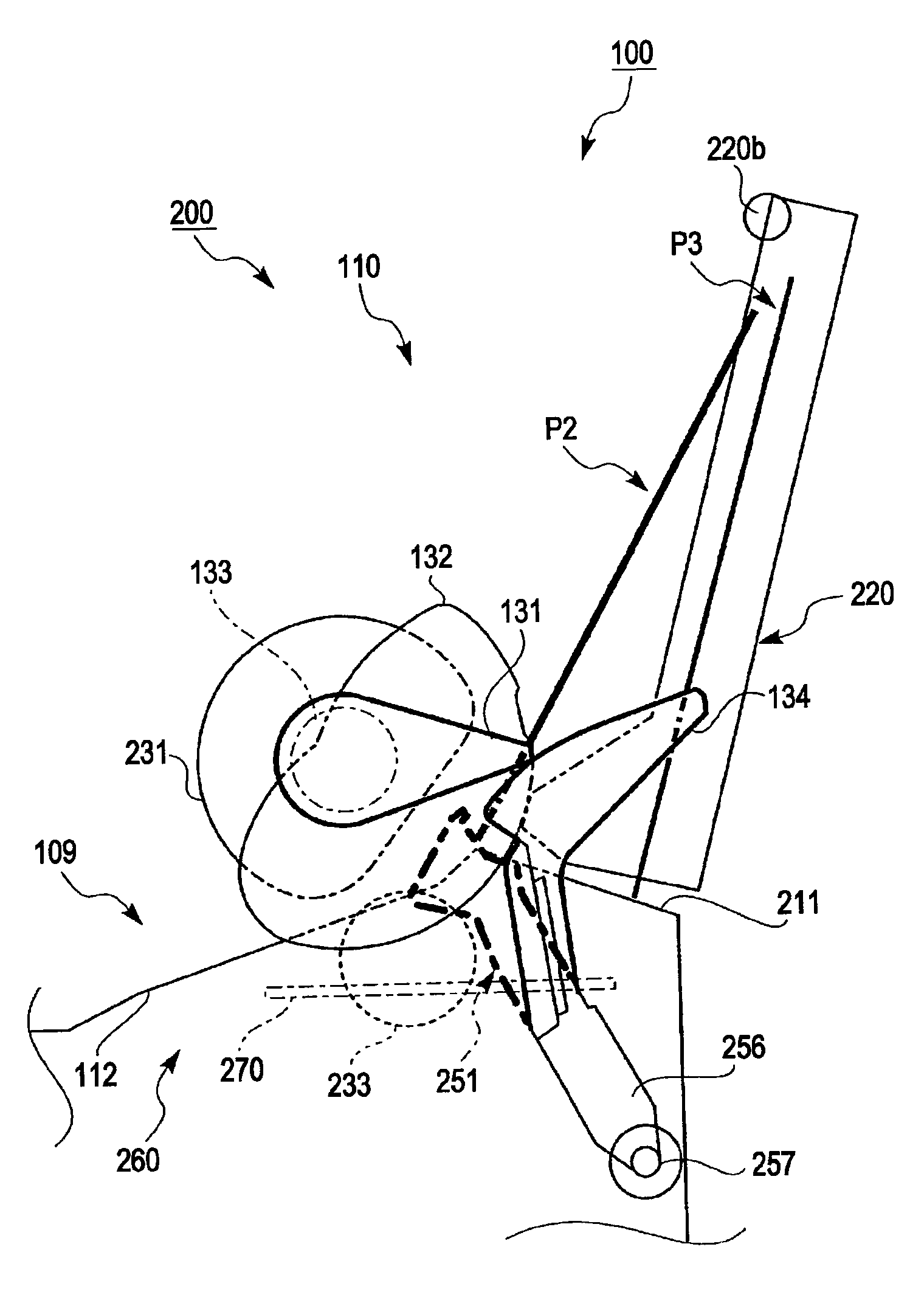
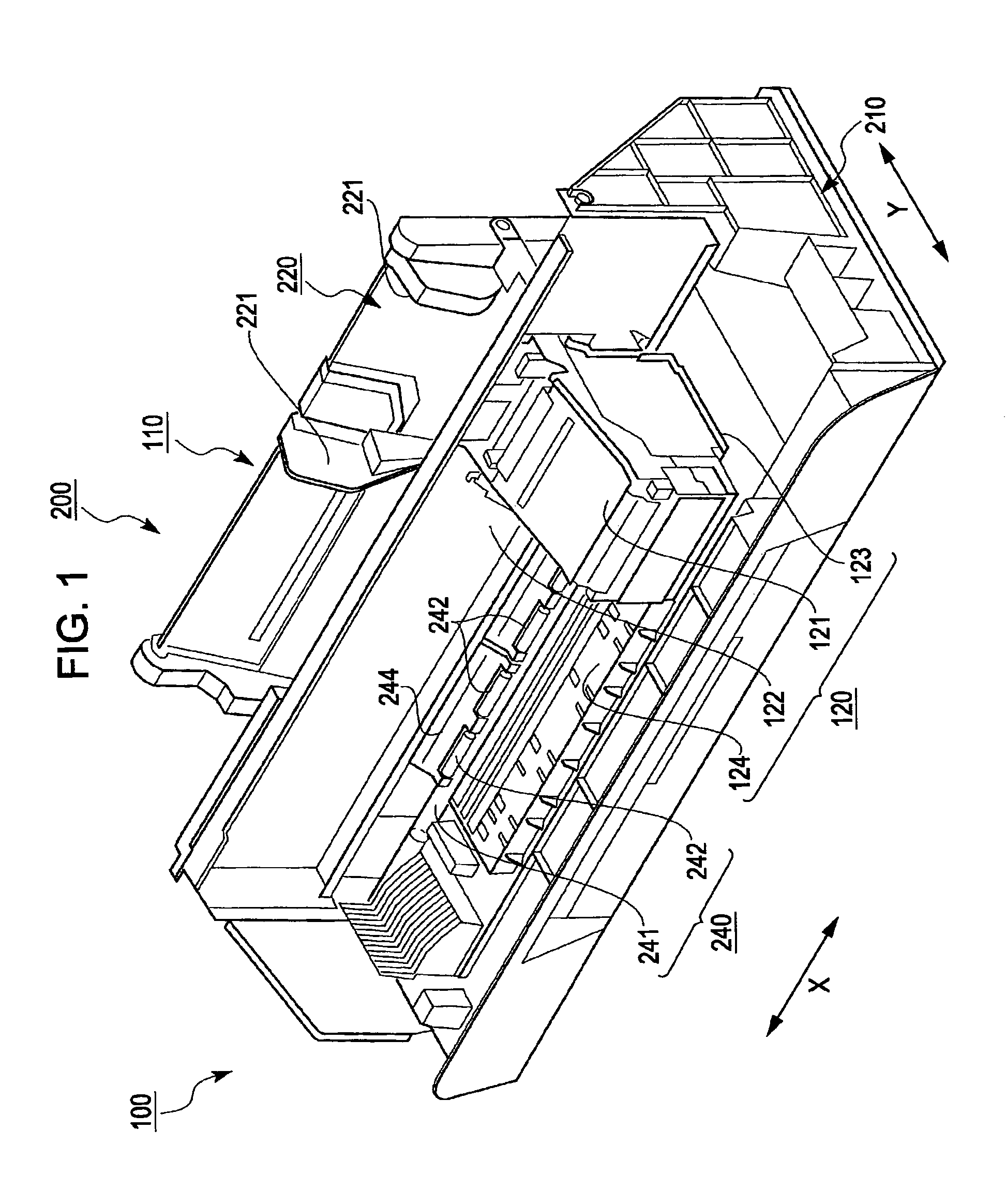
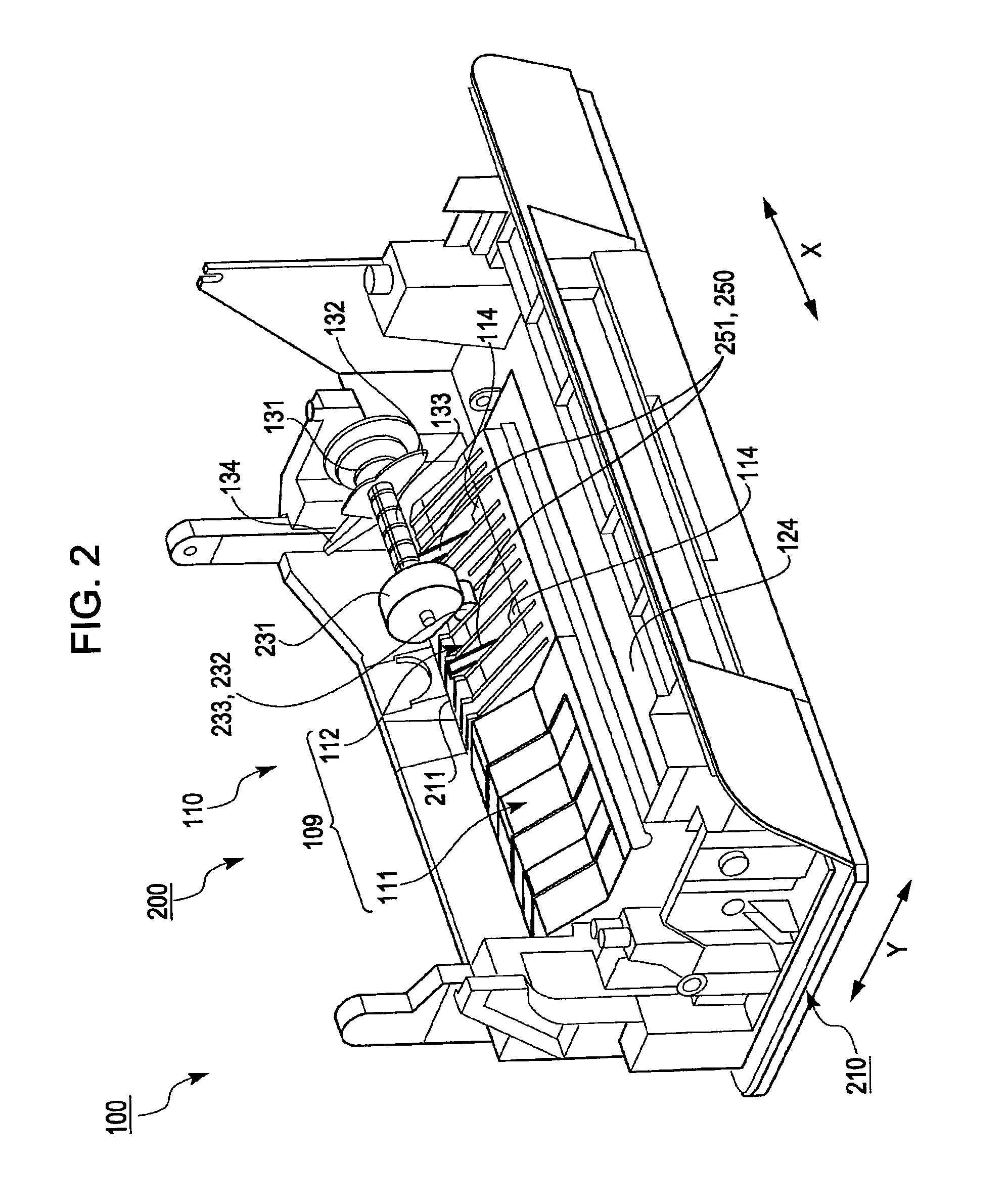
[0053]A feed device according to an embodiment of the invention and a recording apparatus being one example of a liquid ejecting apparatus that uses the feed device are described below. Firstly, a general structure of an ink jet printer as the best mode for carrying out a liquid ejecting apparatus according to an embodiment of the invention and a recording apparatus being one example thereof is schematically described below with reference to the drawings.

[0054]FIG. 1 is a general perspective view that illustrates the inside of an ink jet printer according to an embodiment of the invention. FIG. 2 is a general perspective view of the ink jet printer illustrated in FIG. 1 with a recording unit removed. FIG. 3 is a general frontal view of the recording apparatus illustrated in FIG. 2 with a feed roller removed.

[0055]As illustrated in FIGS. 1 to 3, an ink jet printer 100 includes a feed unit 110 which feeds a recording medium P being one example of a liquid ejecting target (hereinafter ...


PUM


Abstract

A feed device includes a feed roller and a return lever member. The feed roller picks up a first recording medium from recording media stacked on a stacking unit and feeds the first recording medium downstream via a feed path. The return lever member pushes back upstream a second recording medium that has unnecessarily entered the feed path in feeding the first recording medium downstream. The stacking unit includes an end support portion that supports a leading end of the recording media from below. The return lever member includes a lever unit capable of being protruded into and retracted from the feed path. The lever unit pushes back the second recording medium upstream when protruding into the feed path. The lever unit includes a return operative portion that pushes back the second recording medium upstream and a raising portion that raises the second recording medium above the end support portion.

Description

BACKGROUND[0001]1. Technical Field[0002]The present invention relates to a return lever member, a feed device including the return lever member and a feed roller, a recording apparatus including the feed device, and a liquid ejecting apparatus including the feed device. The feed roller picks up a recording medium from a recording media stacked on a stacking unit and feeds the recording medium downstream via a feed path. The return lever member pushes back upstream another recording medium that has unnecessarily entered the feed path in feeding a necessary recording medium downstream.[0003]A liquid ejecting apparatus used herein is not limited to an ink jet recording apparatus, copier, and facsimile machine, which record information by ejecting ink onto a recording material (e.g., recording paper) from a recording head as a liquid ejecting head. Other examples of the liquid ejecting apparatus include an apparatus that attaches liquid for a specific application, instead of ink, to an ...

Claims


Application Information

Patent Timeline
Patent Type & Authority Patents(United States)
IPC IPC(8): B65H3/52
CPCB41J13/103B65H3/0661B65H3/565B65H2801/12
Inventor NAKASHIMA, HIROKI
Owner SEIKO EPSON CORP
Learn More