Waterproof structure for portion where members are tightened with screw

a technology of waterproof structure and screw, which is applied in the direction of screws, fastening means, washing machines, etc., can solve the problems of reducing the space of the second member, affecting the use of the packing, so as to eliminate the need for a large space

Inactive Publication Date: 2010-06-22
JVC KENWOOD CORP A CORP OF JAPAN
View PDF16 Cites 15 Cited by
  • Summary
  • Abstract
  • Description
  • Claims
  • Application Information

AI Technical Summary

Benefits of technology

[0018]Owing to the waterproof structures for a portion where members are tightened with a screw according to the present invention, the O-ring is pressed by the surface not to be damaged, enabling repeated use. Further, the head of the flat head screw is put in the screw insertion hole of the second member, therefore the head of the screw is not protruded above the second member, eliminating enlargement of a necessary space.

Problems solved by technology

In the conventional waterproof structure for a portion where members are tightened with a screw described above shown in FIG. 4, a bottom surface of the spacer 13 is arranged to abut on the upper surface of the second member 11 for positioning in the vertical direction, which has presented a problem that the surface of the second member 11 was scraped away, when it was made of resin.
Also, the packing 14 gets entangled with a screw portion of the bolt 12, which leads to a problem that the packing 14 becomes unusable, when the bolt 12 is repeatedly tightened.
Further, because the packing 14 gets entangled with the screw portion of the bolt 12 in a process of tightening the bolt 12, the spacer 13 and the packing 14 are rotated together with the bolt 12, so that there arises a problem that the packing 14 is likely to be deformed.
In the waterproof structure for apparatuses proposed in Japanese Patent Application Laid-Open No. 2000-277934 described above, because the O-ring 46 is pressed by the annular projection 35, too strong fastening force on the fixing screw 55 may damage the O-ring 46, causing a problem that the O-ring cannot be repeatedly used.

Method used


Image

  • Waterproof structure for portion where members are tightened with screw
  • Waterproof structure for portion where members are tightened with screw
  • Waterproof structure for portion where members are tightened with screw

Examples


embodiment 1

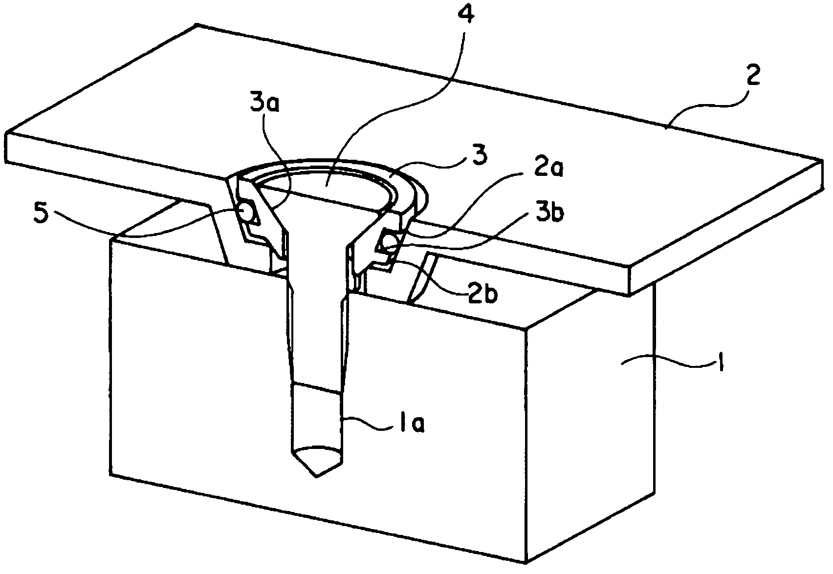
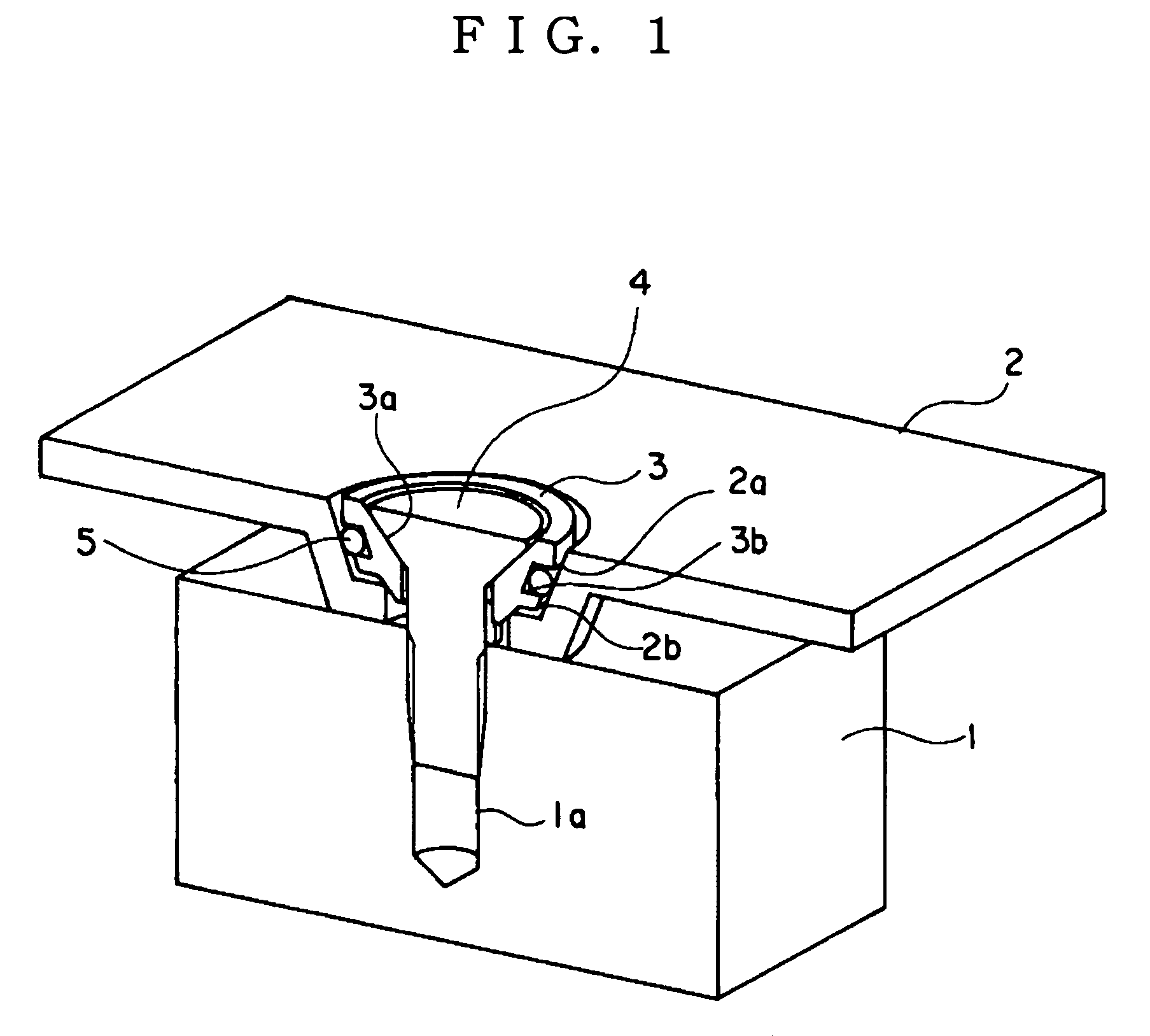
[0024]FIG. 1 is a partially cut away, perspective view illustrating a waterproof structure for a portion where members are tightened, of a first embodiment according to the present invention, illustrating a tightening section where a first member 1 and a second member 2 are fastened with a flat head screw 4, the tightening section being cut out with a plane passing through a central axis of the flat head screw 4.

[0025]In the first member 1 shown in FIG. 1, a screw hole 1a with a bottom is provided, and in the second member 2, a screw insertion hole 2a is provided. The second member 2 is fastened to the first member 1 by screwing the flat head screw 4 which passes through the screw insertion hole 2a into the screw hole 1a with a bottom.

[0026]Then, to form a waterproof structure, a spacer 3 and an O-ring 5 are placed between the flat head screw 4 and the second member 2. In the inside of the spacer 3, a recessed circular conical surface 3a is formed to be in surface contact with a cir...

embodiment 2

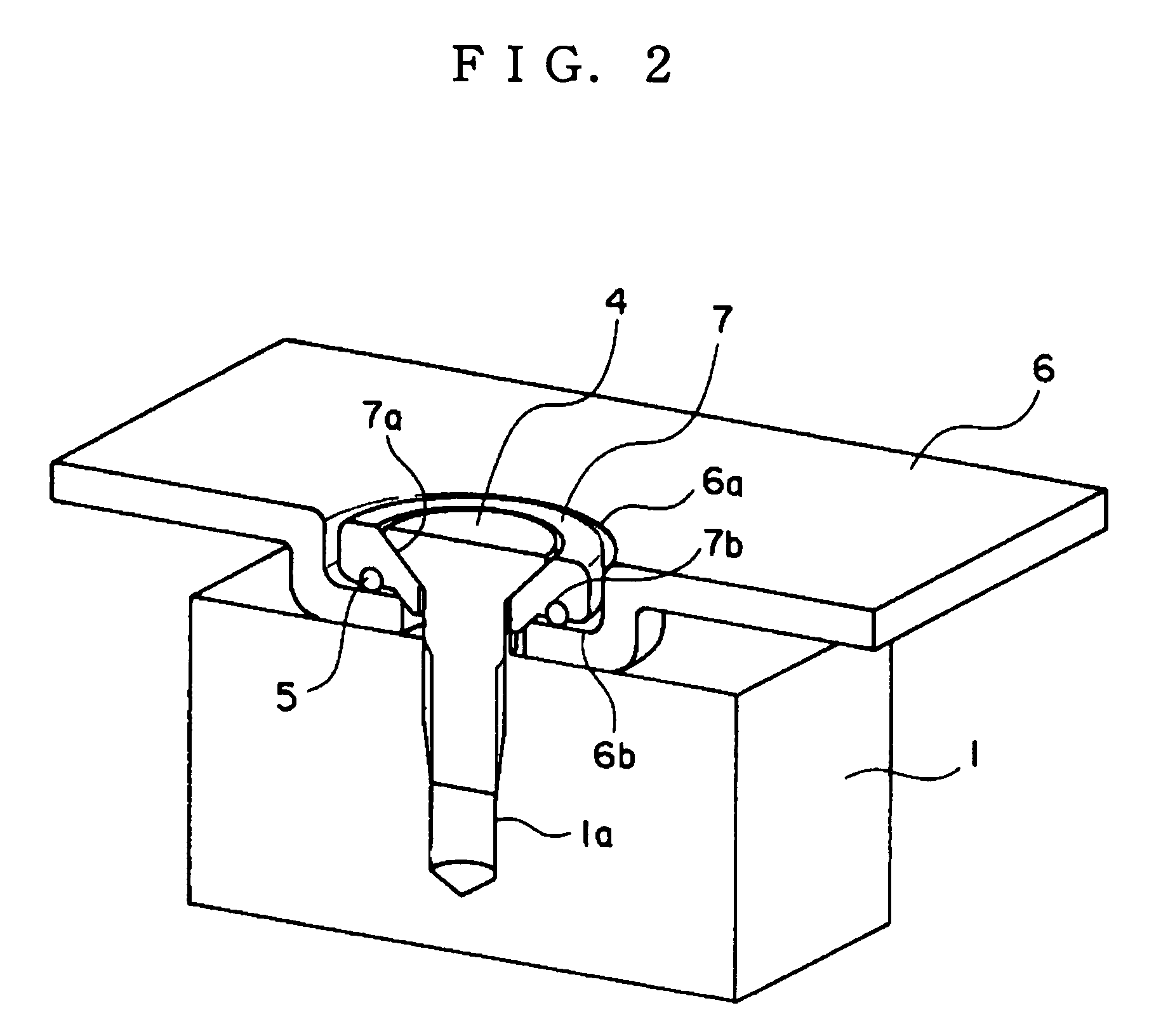
[0030]FIG. 2 is a partially cut away, perspective view illustrating a waterproof structure for a portion where members are tightened, of a second embodiment according to the present invention, illustrating a tightening section where a first member 1 and a second member 6 are fastened with a flat head screw 4, the tightening section being cut out with a plane passing through a central axis of the flat head screw 4.

[0031]In the first member 1 shown in FIG. 2, a screw hole 1a with a bottom is provided, and in the second member 6, a screw insertion hole 6a is provided. The second member 6 is fastened to the first member 1 by screwing the flat head screw 4 which passes through the screw insertion hole 6a into the screw hole 1a with a bottom.

[0032]Then, to form a waterproof structure, a spacer 7 and an O-ring 5 are placed between the flat head screw 4 and the second member 6. In the inside of the spacer 7, a recessed circular conical surface 7a is formed to be in surface contact with a ci...

embodiment 3

[0036]FIG. 3 is a partially cut away, perspective view illustrating a waterproof structure for a portion where members are tightened, which is a third embodiment according to the present invention, illustrating a tightening section where a first member 1 and a second member 8 are fastened with a flat head screw 4, the tightening section being cut out with a plane passing through a central axis of the flat head screw 4.

[0037]In the first member 1 shown in FIG. 3, a screw hole 1a with a bottom is provided, and in the second member 8, a screw insertion hole 8a is provided. The second member 8 is fastened to the first member 1 by screwing the flat head screw 4 which passes through the screw insertion hole 8a into the screw hole 1a with a bottom.

[0038]Then, to form a waterproof structure, a spacer 9 and an O-ring 5 are placed between the flat head screw 4 and the second member 8. In the inside of the spacer 9, a recessed circular conical surface 9a is formed to be in surface contact with...


PUM


Abstract

A waterproof structure for a tightening section where a first member (1) having a screw hole (1a) with a bottom and a second member (2) having a screw insertion hole (2a) are fastened with a screw (4) that is inserted into the screw insertion hole (2a) and screwed to the screw hole (1a). The screw (4) is a flat head screw, and an annular groove (3b) is formed in the outer surface of a spacer (3) having an insertion hole where recessed circular conical surface (3a) is formed. The spacer (3) is fitted in the screw insertion hole (2a) to be in surface contact with a circular conical surface of a head of the flat head screw. The annular groove (3b) is coaxial with the recessed circular conical surface (3a). An O-ring (5) is installed in the annular groove (3b), and the flat head screw (4) is tightened with the spacer (3) placed between first member and the second member, causing the O-ring (5) to be pressed between an inner surface of the annular groove (3b) and a surface of the screw insertion hole of the second member (2). The waterproof structure can be repeatedly used without damaging the members and does not enlarge a necessary space.

Description

TECHNICAL FIELD[0001]The present invention relates to a waterproof structure for a portion where members are tightened with a screw.BACKGROUND ART[0002]FIG. 4 shows an example of a conventional waterproof structure for a portion where members are tightened with a screw. FIG. 4 shows a state of a tightening section where a first member 10 and a second member 11 are fastened with a bolt 12, the tightening section being cut out by a plane passing through a central axis of the bolt 12.[0003]In the first member 10, a screw hole 10a with a bottom is provided, and in the second member 11, a screw insertion hole 11a is provided. The second member 11 is fastened to the first member 10 by screwing the bolt 12 which passes through the screw insertion hole 11a into the screw hole 10a with a bottom.[0004]Then, to form a waterproof structure, a spacer 13 and a packing 14 are placed between the bolt 12 and the second member 11. In addition, FIG. 4 exaggeratedly shows a state in a larger scale befo...

Claims


Application Information

Patent Timeline
Patent Type & Authority Patents(United States)
IPC IPC(8): F16B43/00
CPCF16B43/001F16B5/02F16B35/06Y10S411/915
Inventor MIYOSHI, SACHIYONAITO, KIYOSHI
Owner JVC KENWOOD CORP A CORP OF JAPAN
Why Eureka
Try Eureka