
Sensor networks for monitoring pipelines and power lines

a technology for power lines and sensors, applied in data switching networks, frequency-division multiplexes, instruments, etc., can solve problems such as hazardous terrain that is not easily accessible and hundreds of miles long

Active Publication Date: 2010-04-27
GOOGLE LLC
View PDF134 Cites 239 Cited by
  • Summary
  • Abstract
  • Description
  • Claims
  • Application Information

AI Technical Summary

Benefits of technology

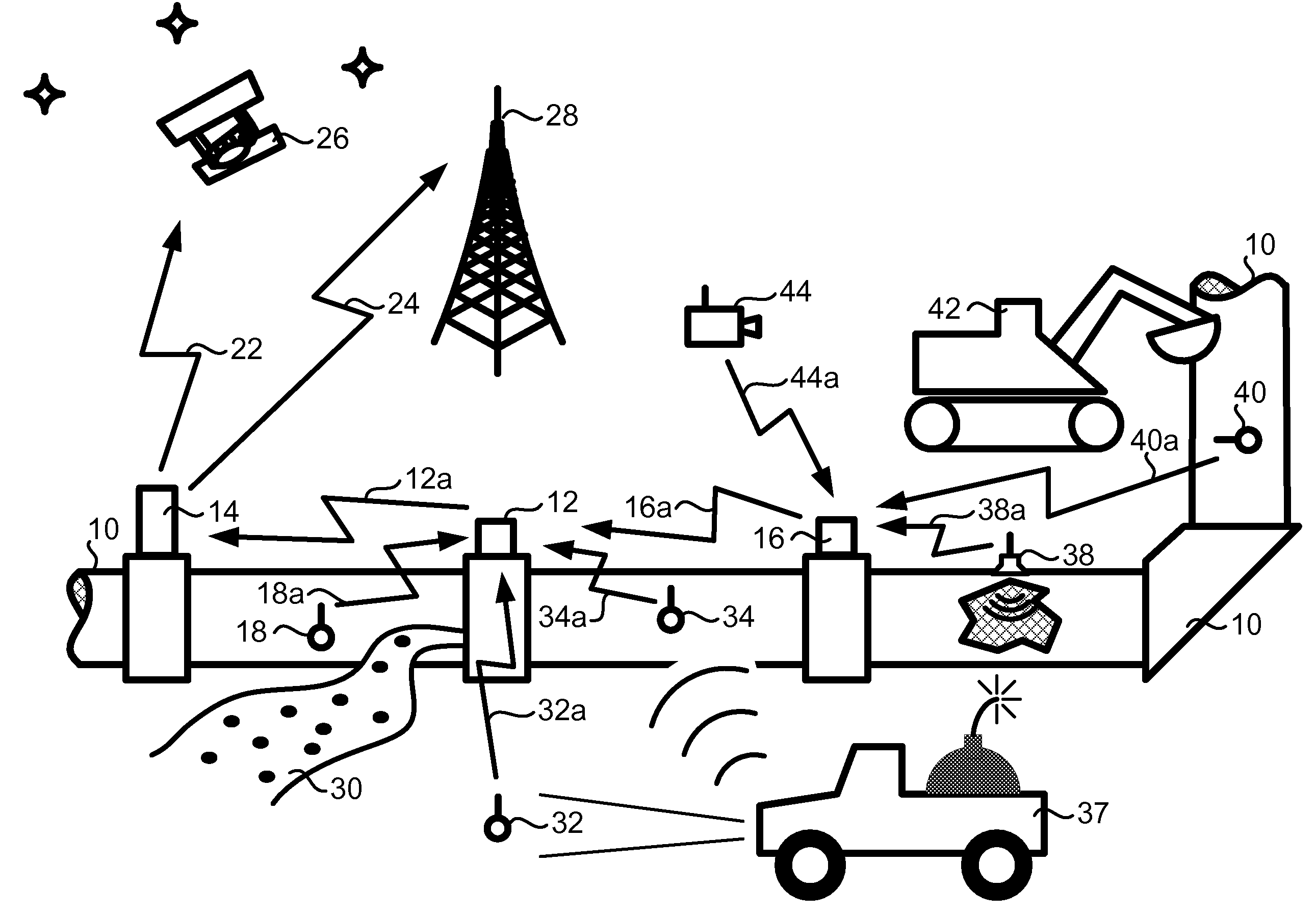
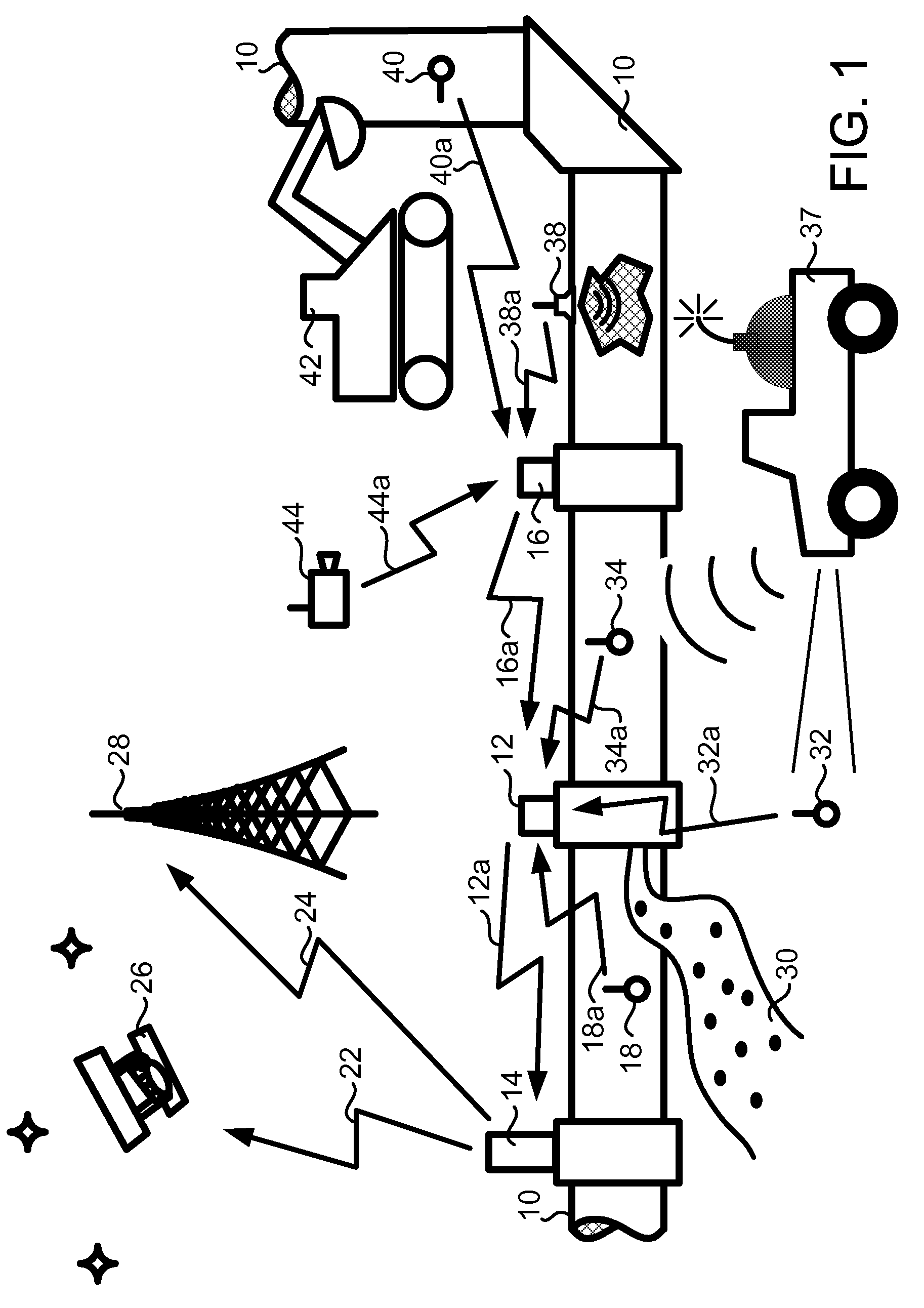
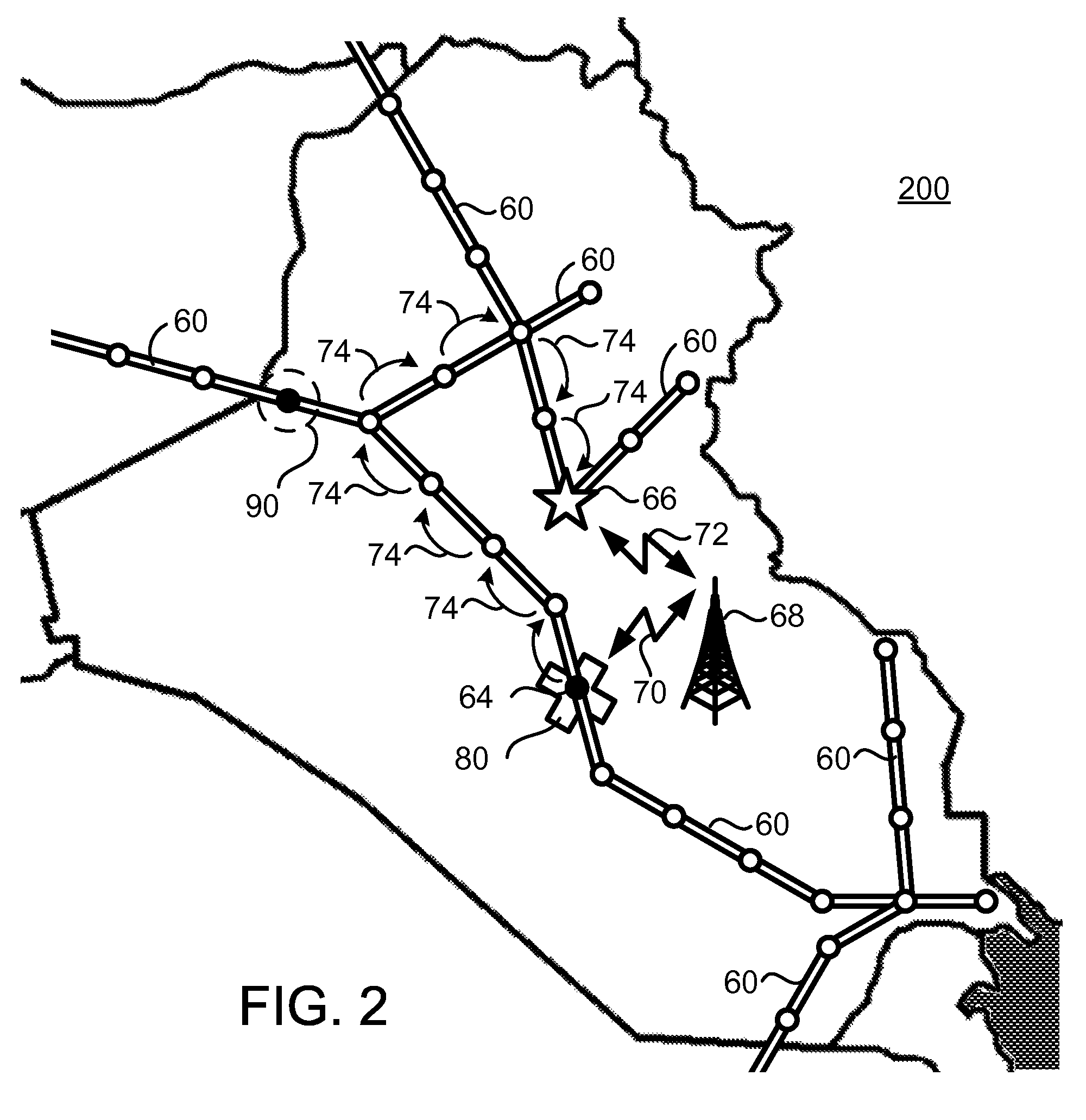
The present invention relates to a system for monitoring pipelines in real-time, using sensors and networks of sensors to detect and track assets such as refined and natural resource materials. The networks can be class-based or remote sensor interface (RSI) networks, which may include low power radio frequency (LPRF) devices such as Bluetooth radios. The sensors can be placed along the pipeline to monitor its condition and detect any threats or leaks. The networks can also include multiple RSIs and a gateway for communication with an external network. The sensors can be various types of sensors such as temperature, humidity, and pressure sensors, as well as activity-monitoring or reconnaissance devices like cameras, microphones, motion detectors, and more. The system allows for continuous, event-based monitoring of pipelines and can be used for security, integrity, and flow control purposes.

Problems solved by technology

Often oil pipelines are hundreds of miles long and transect remote and hazardous terrain that is not easily accessible.

Method used


Image

  • Sensor networks for monitoring pipelines and power lines
  • Sensor networks for monitoring pipelines and power lines
  • Sensor networks for monitoring pipelines and power lines

Examples


Embodiment Construction

[0029]As a preliminary matter, it will readily be understood by one having ordinary skill in the relevant art (“Ordinary Artisan”) that the present invention has broad utility and application. Furthermore, any embodiment discussed and identified as being “preferred” is considered to be part of a best mode contemplated for carrying out the present invention. Other embodiments also may be discussed for additional illustrative purposes in providing a full and enabling disclosure of the present invention. Moreover, many embodiments, such as adaptations, variations, modifications, and equivalent arrangements, will be implicitly disclosed by the embodiments described herein and fall within the scope of the present invention.

[0030]Accordingly, while the present invention is described herein in detail in relation to one or more embodiments, it is to be understood that this disclosure is illustrative and exemplary of the present invention, and is made merely for the purposes of providing a f...


PUM


Abstract

A sensor network for monitoring utility power lines comprises a sensor disposed for monitoring utility power lines, the sensor capable of acquiring data related to the utility power lines and communicating sensor data; a first remote sensor interface (RSI) comprising a data communications device capable of receiving the sensor data communicated from the sensor, and transmitting data relating to the received sensor data; and a data communications device capable of receiving the data transmitted by the first RSI and transmitting data related to the sensor data directly or indirectly to a network external to the sensor network. The sensor network comprises a common designation network.

Description

I. CROSS-REFERENCE TO RELATED APPLICATIONS[0001]The present application is a nonprovisional of, and claims priority under 35 U.S.C. §119(e) to Twitchell, U.S. Provisional Patent Application No. 60 / 709,204 filed Aug. 18, 2005, and Twitchell, U.S. Provisional Patent Application No. 60 / 719,061 filed Sep. 21, 2005. The entire disclosure of these patent applications are hereby incorporated herein by reference.II. INCORPORATION BY REFERENCE[0002]The present application hereby incorporates by reference: U.S. Pat. No. 6,753,775 B2 (titled “Smart Container Monitoring System”); U.S. Pat. No. 6,745,027 B2 (titled “Class Switched Networks for Tracking Articles”); International Patent Application Publication No. WO 2003 / 032501 A2, which international patent application designated the United States and was published in English (titled “Network Formation in Asset Tracking System Based on Asset Class”); International Patent Application Publication No. WO 2003 / 098851 A1, which international patent a...

Claims


Application Information

Patent Timeline
Patent Type & Authority Patents(United States)
IPC IPC(8): G08C17/00
CPCG08B25/009F17D5/06
Inventor TWITCHELL, JR., ROBERT W.
Owner GOOGLE LLC
Learn More