
Buoy-based marine electromagnetic signal acquisition system

a technology of electromagnetic signal acquisition and buoy, which is applied in the field of marine electromagnetic geophysical surveying, can solve the problems of limited natural source electromagnetics for marine applications and no active source in such mt methods

Inactive Publication Date: 2010-04-27
JANSSEN PHARMA NV +1
View PDF40 Cites 71 Cited by
  • Summary
  • Abstract
  • Description
  • Claims
  • Application Information

AI Technical Summary

Benefits of technology

The invention is a sensor cable system for measuring the electromagnetic response of the Earth's subsurface. The system includes a sensor cable deployable on the bottom of a body of water, with multiple electromagnetic sensing devices located at different locations. A control unit is connected to the sensing elements and can receive signals from the sensing elements and compute them to create a statistical measure of the signals. The control unit is placed on a flotation device. The invention also includes a method for acquiring a marine electromagnetic survey by detecting signals in the water and conducting them to processing devices on the surface. The technical effects of the invention are improved accuracy and efficiency in measuring the electromagnetic response of the subsurface, which can aid in energy exploration and production.

Problems solved by technology

Hereto, natural source electromagnetics for marine applications has been restricted to autonomous recording stations.
There is no active source in such MT methods, which rely upon naturally occurring EM fields.

Method used


Image

  • Buoy-based marine electromagnetic signal acquisition system
  • Buoy-based marine electromagnetic signal acquisition system
  • Buoy-based marine electromagnetic signal acquisition system

Examples


Embodiment Construction

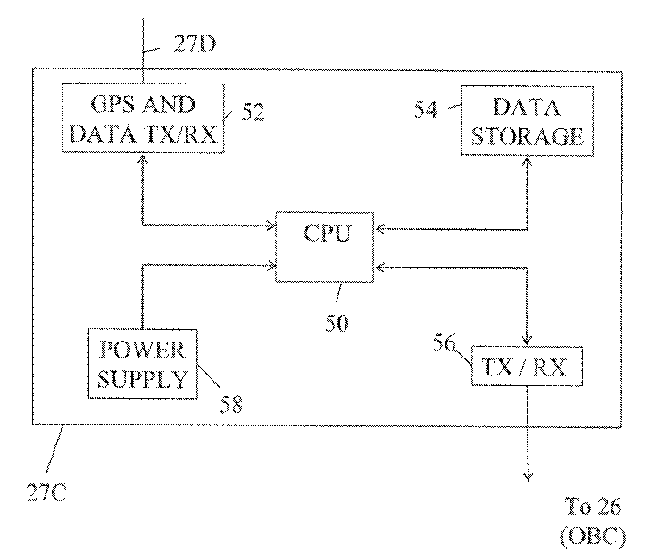
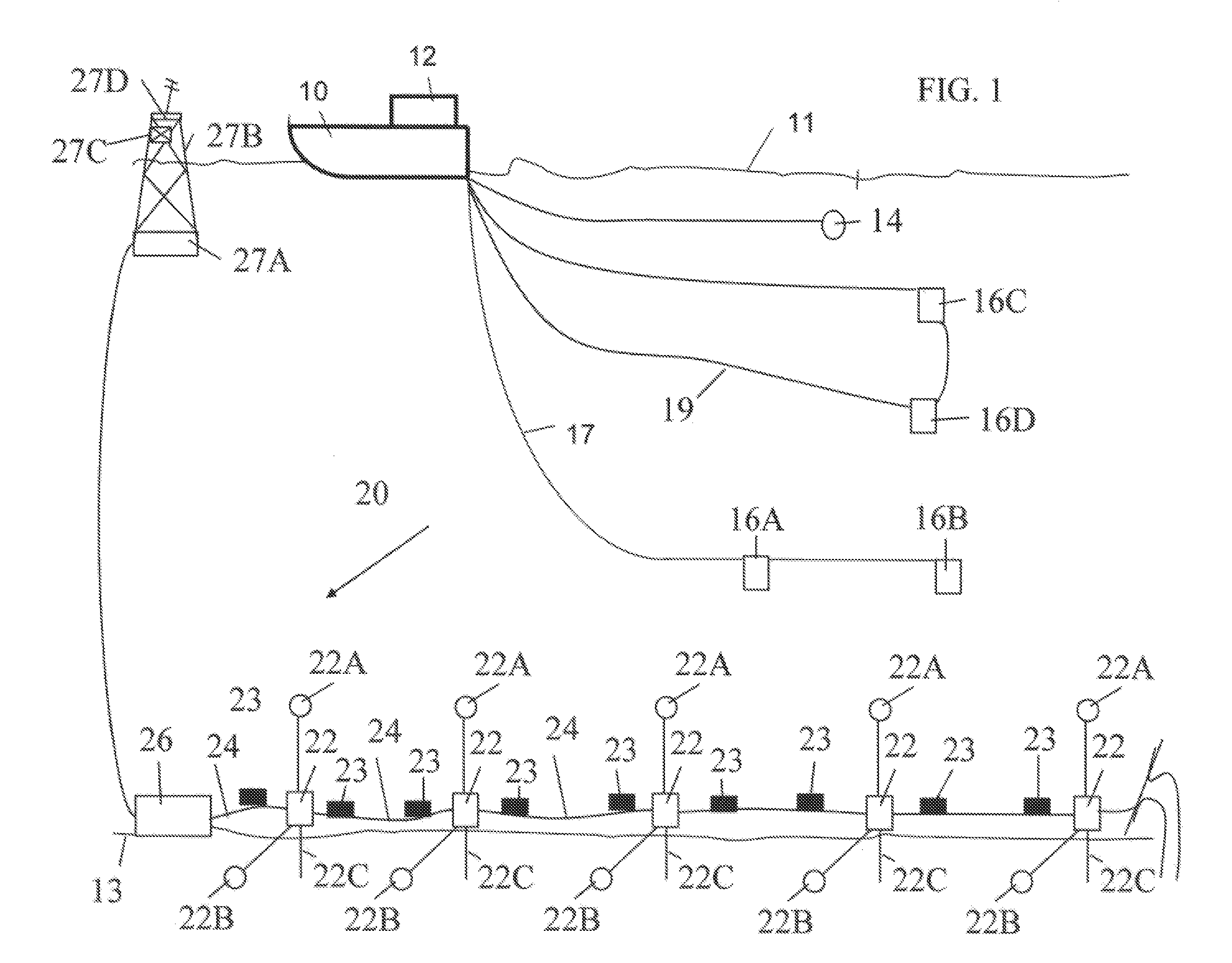
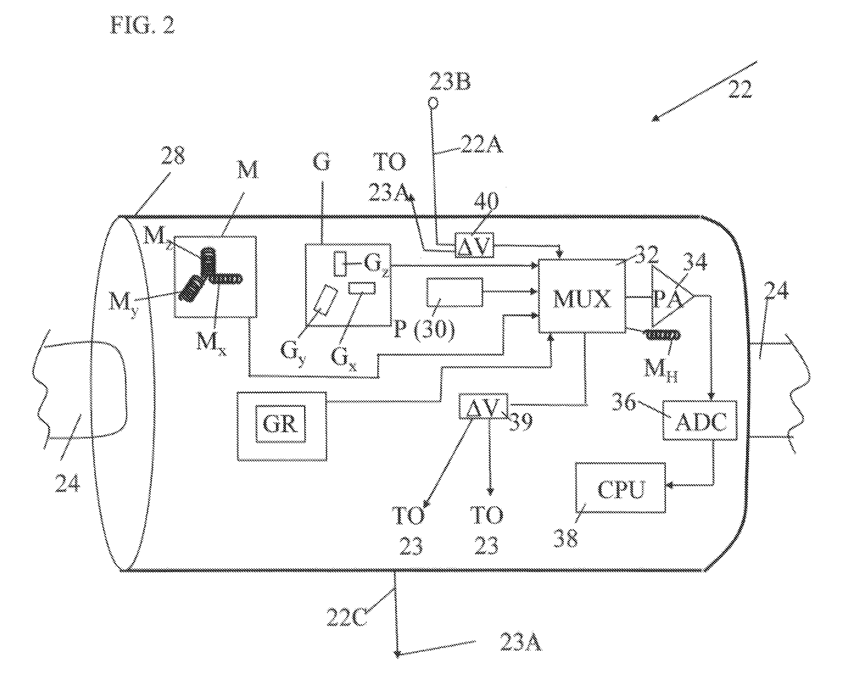
[0061]One example of a marine electromagnetic (EM) survey acquisition system is shown schematically in FIG. 1. The system may include a survey vessel 10 that moves along the surface of a body of water 11 such as a lake or the ocean. The survey vessel 10 includes thereon certain equipment, shown generally at 12 and referred to for convenience as a “recording system.” The recording system 12 may include (none of the following shown separately for clarity of the illustration) navigation devices, source actuation and control equipment, and devices for recording and processing measurements made by various sensors in the acquisition system. The vessel 10 may tow a seismic energy source 14 such as an air gun or an array of such air guns, a vertical electric dipole “source” antenna 19 including vertically spaced apart electrodes 16C, 16D and a horizontal electric dipole “source” antenna 17, which may include horizontally spaced apart electrodes 16A, 16B. The vertical electrodes 16C, 16D are...


PUM


Abstract

A sensor cable system for measuring electromagnetic response of the Earth's subsurface includes a sensor cable deployable on the bottom of a body of water. The sensor cable has a plurality of electromagnetic sensing devices thereon at spaced apart locations. A system control unit is in signal communication with the sensing elements. The system control unit includes a transceiver for communicating signals to and from a corresponding sensor cable system. The system control unit includes a global positioning system signal receiver. The system control unit includes a processor configurable to receive signals detected by sensing elements in the corresponding sensor cable system. The processor is configurable to compute stacked signals from the sensing elements in the sensor cable and from sensing elements in the corresponding system. The processor is configurable to calculate a statistical measure of the stacked signals. The system control unit is disposed in a flotation device.

Description

CROSS-REFERENCE TO RELATED APPLICATIONS[0001]Not applicable.STATEMENT REGARDING FEDERALLY SPONSORED RESEARCH OR DEVELOPMENT[0002]Not applicable.BACKGROUND OF THE INVENTION[0003]1. Field of the Invention[0004]The invention relates generally to the field of marine electromagnetic geophysical surveying. More specifically, the invention relates to cables and related apparatus for acquiring, recording and transmitting electromagnetic signals produced for subsurface Earth surveying.[0005]2. Background Art[0006]Electromagnetic geophysical surveying includes “controlled source” and natural source electromagnetic surveying. Controlled source electromagnetic surveying includes imparting an electric field or a magnetic field into the Earth formations, those formations being below the sea floor in marine surveys, and measuring electric field amplitude and / or amplitude of magnetic fields by measuring voltage differences induced in electrodes, antennas and / or interrogating magnetometers disposed ...

Claims


Application Information

Patent Timeline
Patent Type & Authority Patents(United States)
IPC IPC(8): G01V3/00G01V3/08
CPCG01V3/12G01V3/083Y02A90/30
Inventor STRACK, KURT M.MCMILLAN, IANHELWIG, STEFAN L.
Owner JANSSEN PHARMA NV
Learn More