
Remotely activated mitral annuloplasty system and methods

a mitral annuloplasty and remote activation technology, applied in the field of intravascular prosthesis, can solve the problems of congestive heart failure, pulmonary venous pressure and cardiac output reduction, and the vicious cycle of progressive enlargement and worsening of mitral regurgitation

Inactive Publication Date: 2010-04-13
EDWARDS LIFESCIENCES AG
View PDF208 Cites 111 Cited by
  • Summary
  • Abstract
  • Description
  • Claims
  • Application Information

AI Technical Summary

Benefits of technology

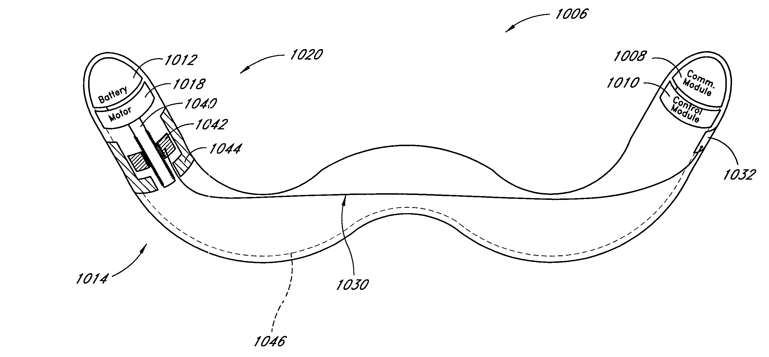
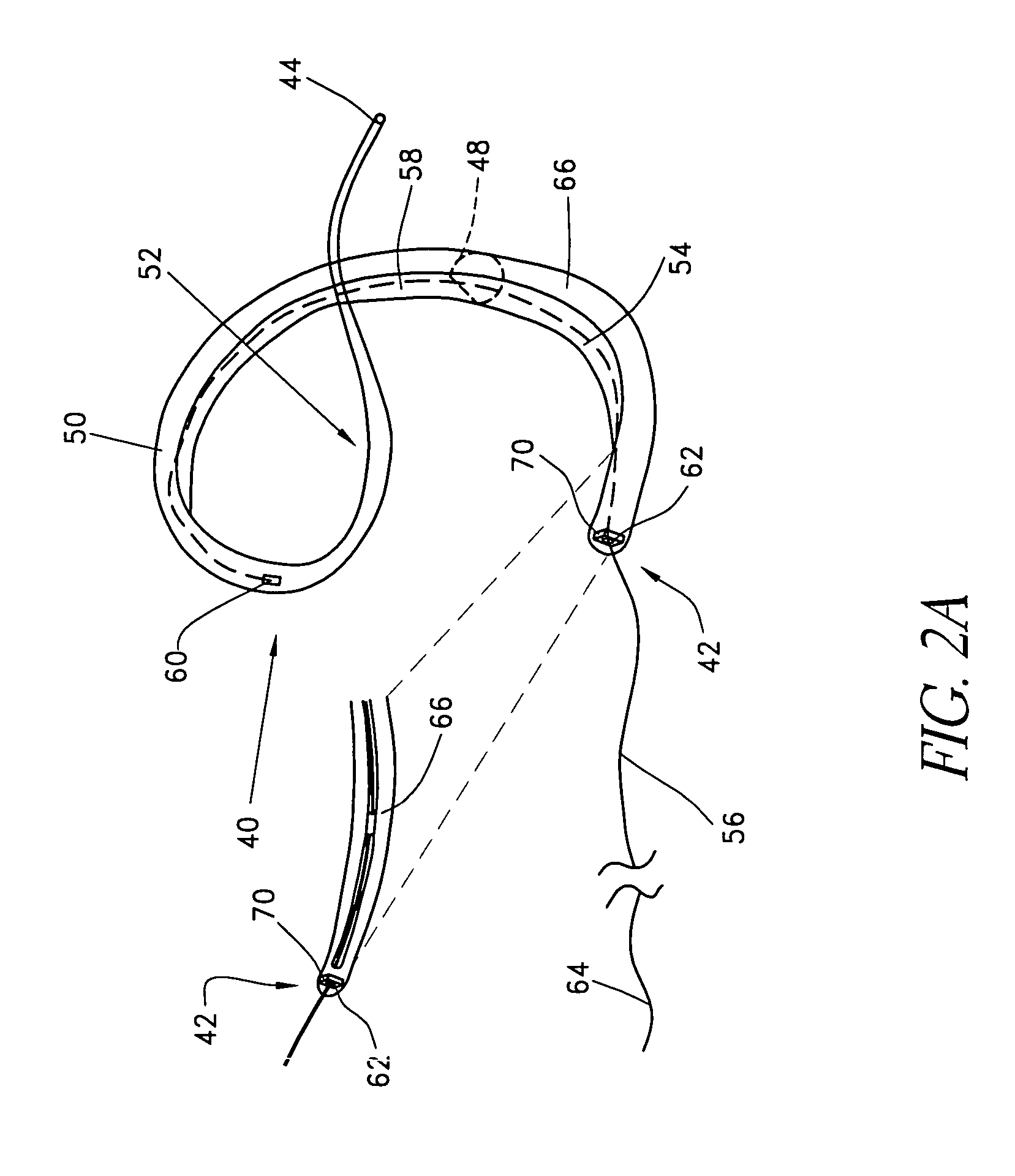
The present invention provides an implant for applying pressure to the mitral valve annulus of a patient. The implant is adjustable between a first configuration for positioning and a second configuration for applying pressure. It includes an electronically driven actuator for adjusting the implant. The implant can be advanced into a "c" configuration for applying pressure on the posterior leaflet of the mitral valve. The implant can be removably attached to a deployment catheter and is adjustable using an external control. The invention also includes a medical apparatus for remodeling the mitral valve annulus, an implant for positioning within a patient, and a method of manipulating the mitral valve. The technical effects of the invention include improved treatment for mitral valve regurgitation and improved heart function.

Problems solved by technology

The resulting increase in pulmonary venous pressure and reduction in cardiac output cause congestive heart failure.
This in turn, causes volume overload that exacerbates the myopathy, leading to a vicious cycle of progressive enlargement and worsening mitral regurgitation.
Although mitral valve repair and replacement can successfully treat many patients with mitral valvular insufficiency, techniques currently in use are attended by significant morbidity and mortality.
However, the morbidity, risks and expense of surgical annuloplasty are very high in patients with cardiomyopathy and congestive heart failure.
These techniques may provide some benefits over open chest procedures, but they are still attended by significant morbidity and mortality risks.
In addition, delivery catheters for implantable devices are large and stiff, and they can influence the position and performance of a mitral annuloplasty implant while they are connected to the implant.

Method used


Image

  • Remotely activated mitral annuloplasty system and methods
  • Remotely activated mitral annuloplasty system and methods
  • Remotely activated mitral annuloplasty system and methods

Examples


Embodiment Construction

[0111]Preferred embodiments of the present invention include a method and apparatus for performing mitral annuloplasty and remodeling of the left ventricle using a device that may be introduced percutaneously, and placed within the coronary venous system of the heart. The device exerts compressive force on the mitral annulus and left ventricle, reducing the severity of mitral regurgitation and the size of the left ventricular cavity. The device thus enables reduction of the mitral annulus and constraint of the diastolic expansion of the left ventricle yet without the morbidity and other risks associated with open chest surgery. Additional details are disclosed in the parent application Ser. No. 10 / 066,302, filed on Jan. 30, 2002, the disclosure of which is incorporated in its entirety herein by reference.

[0112]The present inventors have determined that the coronary sinus and veins provide an ideal conduit for the positioning of an intravascular prosthesis, or implant, for remodeling...


PUM


Abstract

Disclosed are implants and methods for remote remodeling of a mitral valve annulus. The implant comprises a body transformable from a flexible configuration for navigation to a treatment site, to a remodeling configuration for, in one application, applying pressure to the posterior leaflet of the mitral valve. On board electronics allow post deployment adjustment of the implant.

Description

RELATED APPLICATIONS[0001]This application is a continuation-in-part of U.S. application Ser. No. 10 / 634,655, filed Aug. 5, 2003, now U.S. Pat. No. 7,011,682 which claims priority from U.S. Provisional No. 60 / 429,281, filed Nov. 25, 2002, and which is a continuation-in-part of U.S. application Ser. No. 10 / 066,302, filed Jan. 30, 2002, now U.S. Pat. No. 6,989,028, which claims priority from U.S. Provisional No. 60 / 265,995, filed Feb. 1, 2001, and which is a continuation-in-part of U.S. application Ser. No. 09 / 774,869, filed Jan. 30, 2001, now U.S. Pat. No. 6,537,314, which is a continuation-in-part of U.S. application Ser. No. 09 / 494,233, filed Jan. 30, 2000, now U.S. Pat. No. 6,402,781 all of which are incorporated by reference herein. This application also claims priority from U.S. Provisional No. 60 / 488,334, filed Jul. 18, 2003, which is incorporated by reference herein.BACKGROUND OF THE INVENTION[0002]1. Field of the Invention[0003]The present invention relates to intravascular p...

Claims


Application Information

Patent Timeline
Patent Type & Authority Patents(United States)
IPC IPC(8): A61F2/24A61B5/00A61F2/02
CPCA61B5/6882A61F2/2466A61F2/2451A61B2560/0219A61F2250/0001
Inventor LASHINSKI, RANDALL T.HOFFMANN, GERARD VONKUSLEIKA, RICHARD S.FORMAN, MICHAEL R.TAYLOR, DAVID MARK
Owner EDWARDS LIFESCIENCES AG
Learn More