
Impact tools with slidable grip

a technology of impact tools and grips, which is applied in the field of hand-operated tools to achieve the effects of convenient, safe and accurate use, and improved accuracy

Inactive Publication Date: 2010-04-13
TOUCHETTE SHANE M
View PDF9 Cites 13 Cited by
  • Summary
  • Abstract
  • Description
  • Claims
  • Application Information

AI Technical Summary

Benefits of technology

"The present invention provides a way to make tools that are more accurate, easy, and safe to use. The invention includes a movable grip on the handle of the tool, which the user can grasp with their hand and move in the same direction as the tool. This allows for a more natural and smooth movement of the tool. The movable grip is a rigid sleeve that slides along the handle and does not rotate or shift in a way that would affect the direction or orientation of the tool head. The invention also includes a rotation-prevention system that prevents the tool handle from rotating during use, which improves the accuracy and safety of the swing. Overall, the invention makes tools that are more effective and efficient, and reduces the need for multiple swings to complete a task."

Problems solved by technology

By using this movable grip, the user may move his hand relative to the handle, relative to the tool head, and relative to his / her other hand, in a direction and manner much like the user's natural hand movement would be during normal use of the tool, except that the preferred moveable grip does not allow significant rotation of the tool in the user's hands and does not allow significant transverse shifting of the tool relative to the moveable grip.
Preferably, also, the fit of the sleeve on the handle is not so tight as to hinder longitudinal sliding, but is tight / snug enough to not allow rotation and to not allow significant transverse movement of the handle in the moveable grip.

Method used


Image

  • Impact tools with slidable grip
  • Impact tools with slidable grip
  • Impact tools with slidable grip

Examples


Embodiment Construction

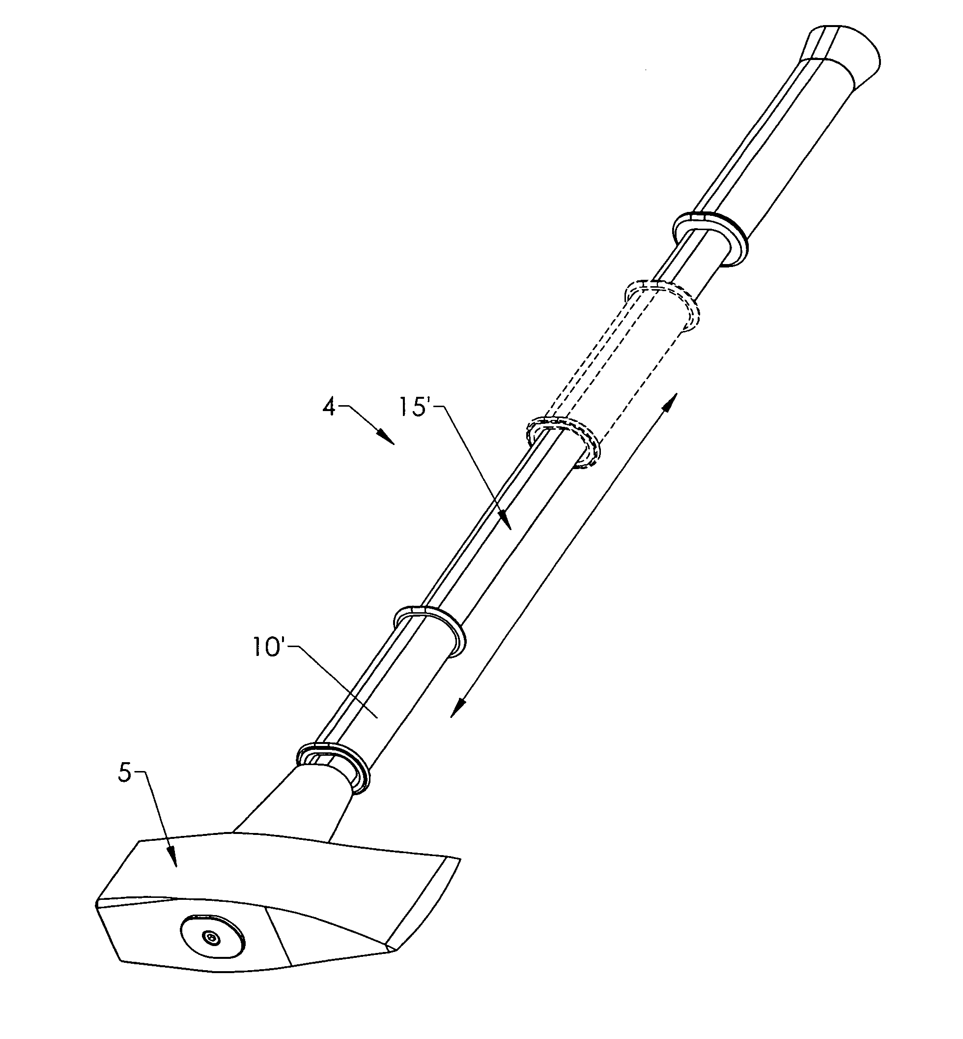
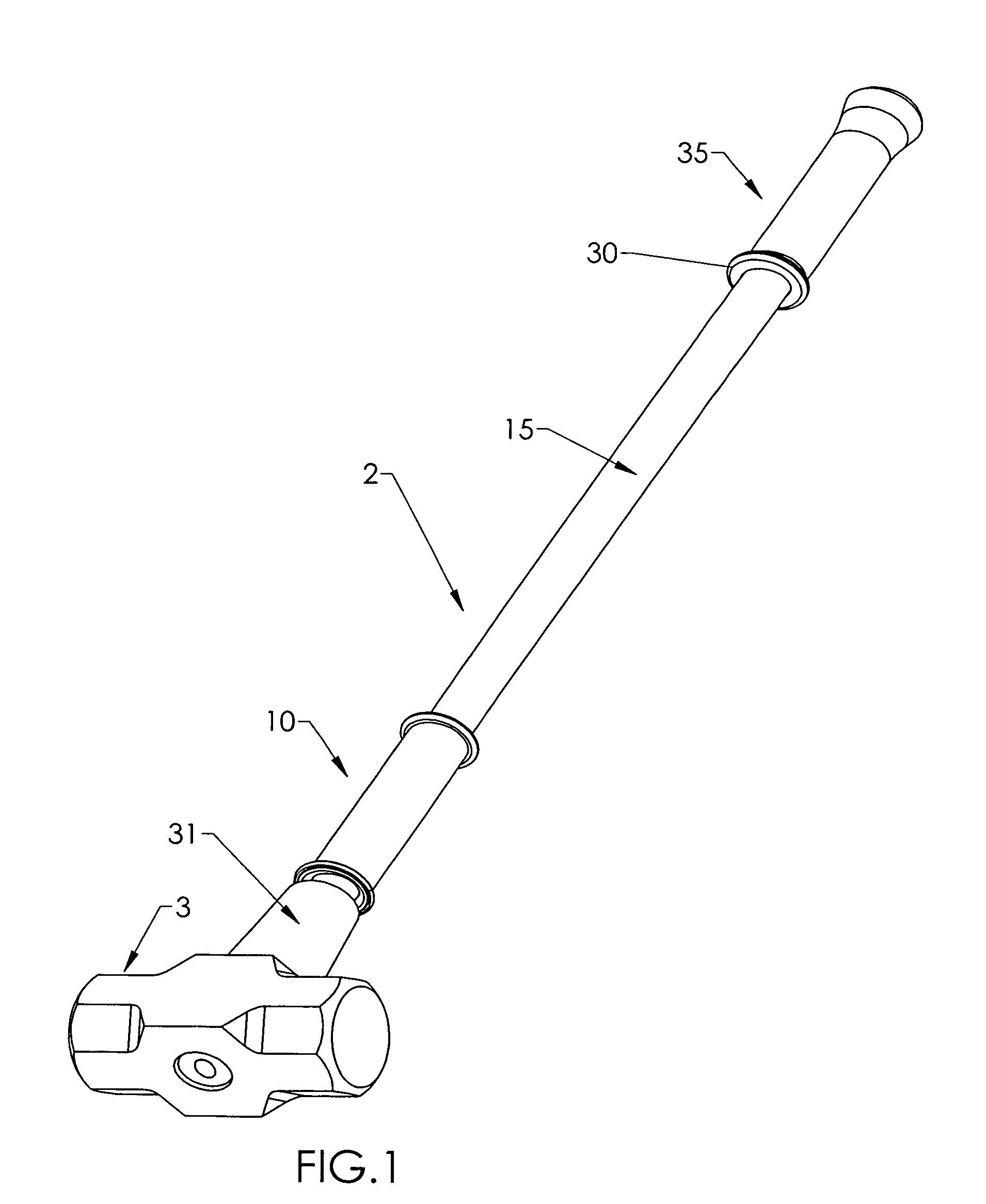
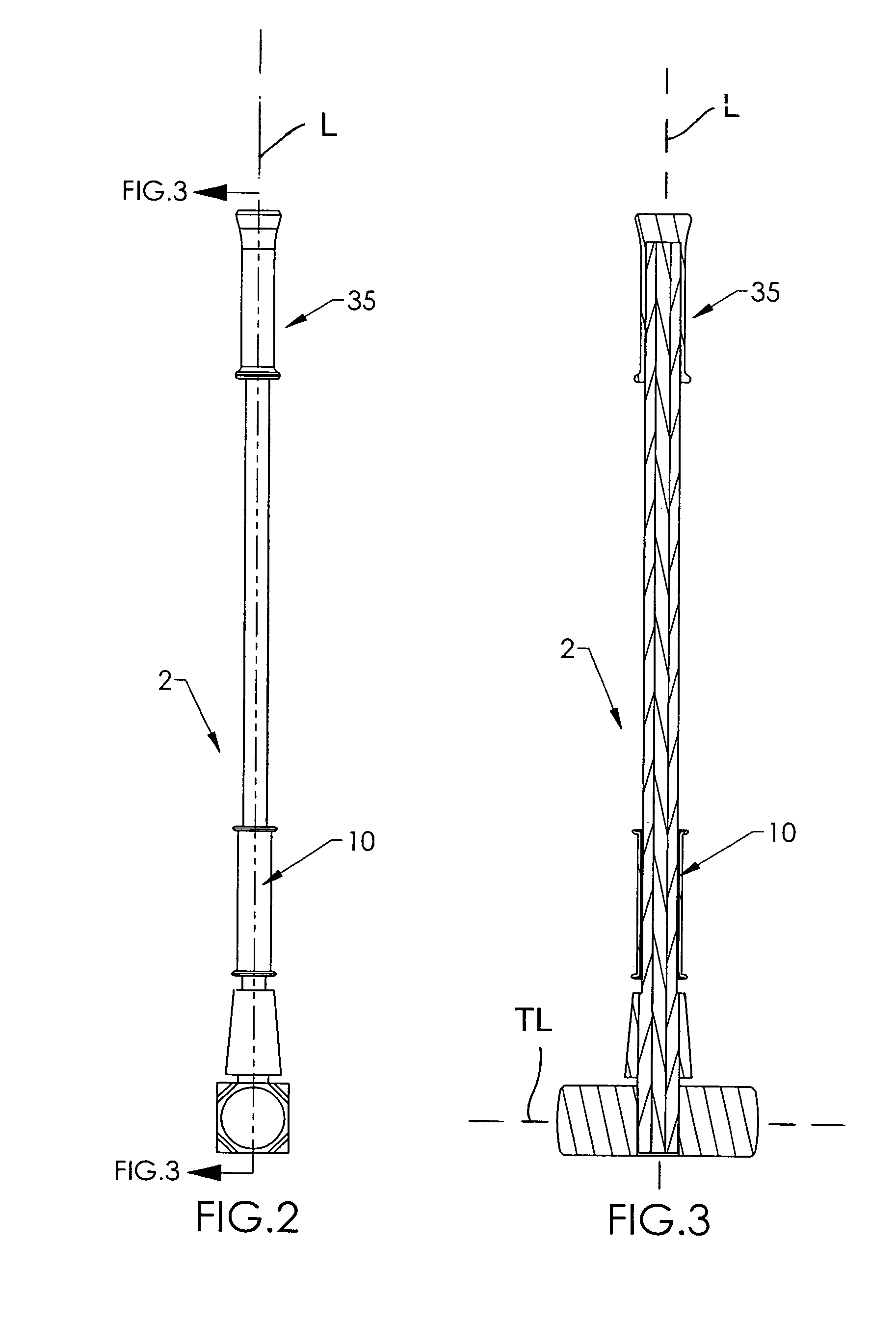
[0045]Referring to the Figures, there are shown several, but not the only, embodiments of the invented moveable grip system for hammer, axis, pick, chisel, cutting tools, and other impact tools, including but not limited to those tools that are portrayed and / or described in this document. For the purposes of this description and the claims, the term “impact tool” includes hitting, cutting, chipping, and other tools that are used by swinging the tool at a target, wherein said swing has a component of motion that is non-parallel to the longitudinal axis of the tool. The preferred embodiments are not used with tools such as “slide hammers” that are intended for impact in a direction parallel to the longitudinal axis of the handle In other words, the preferred embodiments are not used in a manner that involves the user holding the grip in one hand and then “punching” or sliding the handle through the grip toward the work-piece to hit, punch, or pull the tool in a direction parallel to t...


PUM


Abstract

Tools and methods of making tools that are swung toward a work-piece are more accurate and / or safer to use because of a moveable grip provided on the tool handle. The tool handle slides through the moveable grip, with minimal or no rotation or shifting relative to the grip. The movable grip eliminates the need for the forward hand of the user to loosen its grip during portions or all of the swing, eliminates the need for the hand itself to slide along the surface of the handle, and, importantly, greatly reduces or eliminates the chance that the tool and the impact head of the tool hand will rotate or shift relative to user's hand(s). The moveable grip and handle are preferably rigid and hard and mated in shape and size so that rotation and shifting is reduced or eliminated. The preferred embodiment includes one or more control members for retaining or latching the moveable grip in one or more desired locations on the handle, so that the moveable grip may be prevented from sliding along the handle until the user desires it to slide.

Description

[0001]This application claims priority of U.S. Ser. No. 60 / 873,065, filed Dec. 5, 2006; and also U.S. Ser. No. 60 / 944,869, filed Jun. 19, 2007, the entire disclosures of which are incorporated herein by this reference.BACKGROUND OF THE INVENTION[0002]1. Field of the Invention[0003]The present invention relates generally to hand-operated tools, and especially tools that a user swings to make an impact upon a work-piece, whether the impact is for hitting, chipping, or cutting the work-piece. The present invention relates more especially to sledge hammers, axes, hatchets, picks, adzes, pulaskis, pick-axes, or other hitting, picking, chipping, or cutting tools that are moved, during use, in a direction including at least a component that is transverse to the longitudinal axis of the tool handle.[0004]2. Background and Related Art[0005]Traditional sledge hammers, picks, axes, and other impact tools that are swung, comprise an elongated handle and an impact, pick, chipping, or cutting hea...

Claims


Application Information

Patent Timeline
Patent Type & Authority Patents(United States)
IPC IPC(8): B25G1/10
CPCB25D1/14B25D7/00B26B23/00B25G1/06Y10T16/476
Inventor TOUCHETTE, SHANE M.
Owner TOUCHETTE SHANE M
Learn More