
Rotary locking mechanism for outside vehicle door handle

a technology for locking mechanisms and vehicles, applied in the direction of accident situation locks, carpet fasteners, dwelling equipment, etc., can solve the problems of inadvertent door opening, ratcheting to release a striker, and inadvertent door opening

Inactive Publication Date: 2010-03-30
INTIER AUTOMATIVE CLOSURES INC
View PDF21 Cites 18 Cited by
  • Summary
  • Abstract
  • Description
  • Claims
  • Application Information

AI Technical Summary

Benefits of technology

[0007]According to yet another aspect of the invention, a locking device is provided for preventing a motor vehicle door from opening when a portion of a main door latch moves with acceleration above a predetermined threshold relative to a base thereof. The locking device includes a plurality of teeth fixedly secured to the base. A pawl is rotatably coupled to the portion of the main door latch. An inertia element is rotatably coupled to the pawl such that upon acceleration above the predetermined threshold the inertia element lags rotation of the portion of the main door latch to stop movement of the portion of the main door latch relative to the base and prevent the door from opening.

Problems solved by technology

This pivoting of the handle portion in response to the high inertia force or sheet metal buckling can cause inadvertent opening of the door, which is undesirable.
For example, any of numerous motor vehicle doors, including side, rear, and sliding doors, can move with acceleration above a predetermined threshold during a motor vehicle impact, which causes a ratchet to release a striker so that the door opens inadvertently.
Further, a door latch is also subject to inadvertently releasing a striker when an element thereof moves with acceleration higher than a predetermined threshold as a result of an impact force.

Method used


Image

  • Rotary locking mechanism for outside vehicle door handle
  • Rotary locking mechanism for outside vehicle door handle
  • Rotary locking mechanism for outside vehicle door handle

Examples


second embodiment

[0035]Referring to FIGS. 8 through 10, wherein like primed reference numerals represent similar elements as those described above, the locking device 30′ is incorporated into a door locking mechanism, generally indicated at 72. The door locking mechanism 72, which can be associated with a side door, a sliding door, or a rear door, includes a base 74 for mounting to a door of a motor vehicle. A fork 76 is rotatably mounted to the base 74 for movement between a latched position, shown in FIGS. 8 and 9, and an unlatched position, shown in FIG. 10. The fork 76 includes a recess 78 for receiving a bolt 80, which is fixedly mounted along a motor vehicle body 81. A spring (not shown) biases the fork 76 into the unlatched position.

[0036]The locking device 30′ includes the plurality of teeth 40′, the inertia element 46′, and the pawl 54′. The plurality of teeth 40′ is disposed along the base 74 adjacent the fork 76. Preferably, a generally arcuate member 84 is fixedly secured to the base 74...

third embodiment

[0040]Referring to FIGS. 11 through 13, wherein like double primed reference numerals represent similar elements as those described above, the locking device 30″ can be utilized with a main door latch, generally shown at 86. The main door latch 86 includes a ratchet 88 having a notch 90 for selectively retaining a striker 92. The ratchet 88 is rotatably mounted about a pivot 94.

[0041]The main door latch 86 also includes a latch pawl 96, which selectively engages a detent surface 98 of the ratchet 88 to maintain the ratchet 88 in a latched position retaining the striker 92. The latch pawl 96 is rotatably mounted about a pivot pin 100 and is biased into engagement with the ratchet 88 by a spring 102. Inside and outside release handles (both not shown) are operably connected to the latch pawl 96 via a cable or rod. Actuation of one of the inside and outside release handles urges the latch pawl 96 against the bias of the spring 102 and out of engagement with the ratchet 88 in order to ...


PUM


Abstract

A locking device is provided for preventing a motor vehicle door from opening when a handle portion of a handle assembly moves with acceleration above a predetermined threshold relative to a base thereof. The locking device includes a lock cup fixedly secured to the base and having a plurality of teeth. The locking device also includes a spool rotatably coupled to the lock cup and operably connected to the handle portion. The spool includes a pawl rotatably mounted thereto. The locking device further includes an inertia element disposed between the lock cup and the spool. The inertia element is coupled to the pawl such that upon the acceleration above the predetermined threshold the inertia element lags rotation of the spool and forces the pawl into engagement with one of the plurality of teeth to stop movement of the handle portion relative to the base and prevent the door from opening.

Description

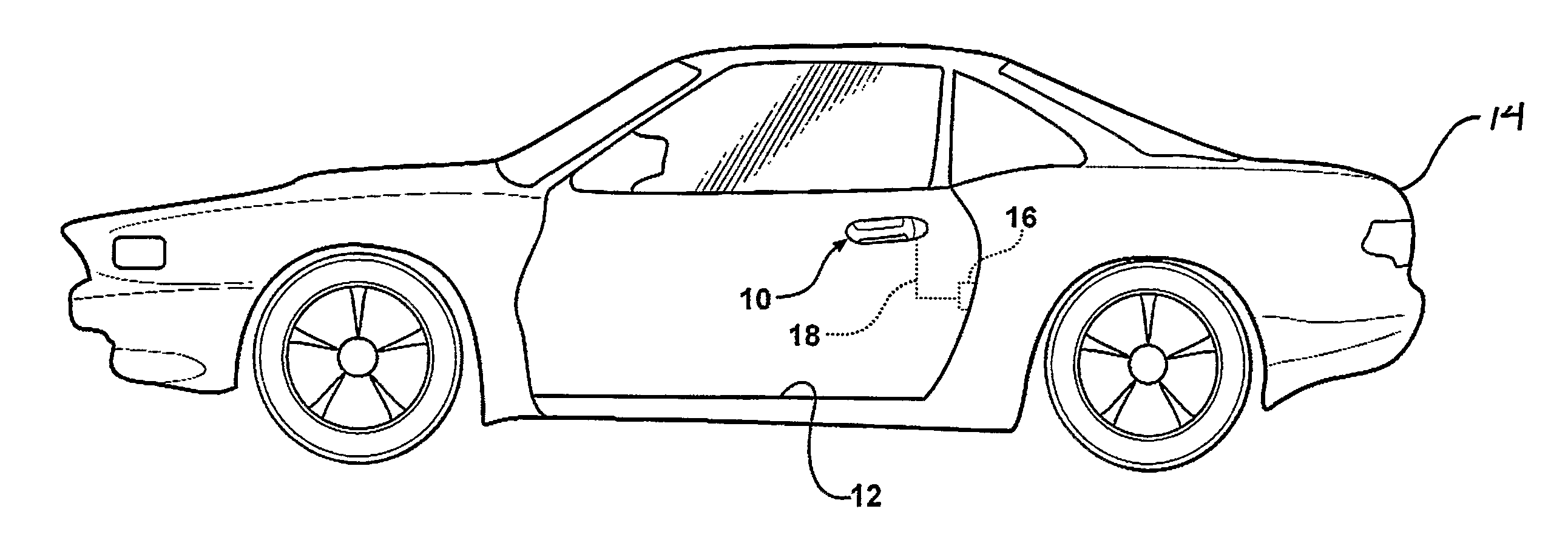
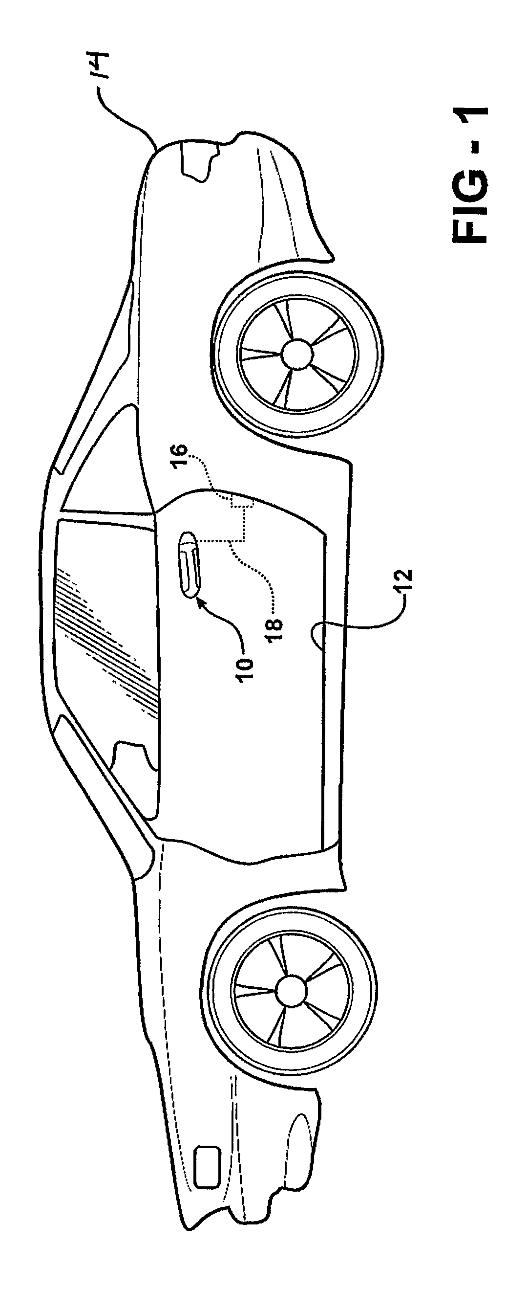
FIELD OF THE INVENTION[0001]The invention relates to a handle assembly for a motor vehicle. More particularly, the invention relates to a locking device for preventing a motor vehicle door from opening when a handle portion of a handle assembly moves with acceleration above a predetermined threshold.DESCRIPTION OF THE RELATED ART[0002]Motor vehicles include at least one outside door handle for releasing a door latch mechanism in order to open a door. Typically, a user actuates the outside door handle by pivoting a handle portion relative to a base. The handle portion may, however, also be pivoted relative to the base when the outside door handle is exposed to a high inertia force or sheet metal buckling, such as may occur during a motor vehicle impact. This pivoting of the handle portion in response to the high inertia force or sheet metal buckling can cause inadvertent opening of the door, which is undesirable.[0003]It is also appreciated that various components other than the outs...

Claims


Application Information

Patent Timeline
Patent Type & Authority Patents(United States)
IPC IPC(8): E05B3/00E05C3/06E05B65/12E05B65/20E05B65/32
CPCE05B77/06E05B85/16E05B85/26Y10S292/65Y10S292/22Y10T70/5221Y10T292/57Y10T292/1047Y10T70/5889E05B85/10E05B77/54
Inventor JANKOWSKI, KRYSTOF P.KAMAL, EHAB KHALID
Owner INTIER AUTOMATIVE CLOSURES INC
Learn More