Muntin clip
a technology of sash window assembly and clip, which is applied in the field of clip, can solve the problems of clip manufacturers, window manufacturers or assemblers, burdening clip manufacturers and window assemblers with large clip inventories, and incurring costs associated with maintaining and otherwise dealing with large and varied inventories
- Summary
- Abstract
- Description
- Claims
- Application Information
AI Technical Summary
Benefits of technology
Problems solved by technology
Method used
Image
Examples
embodiment 400
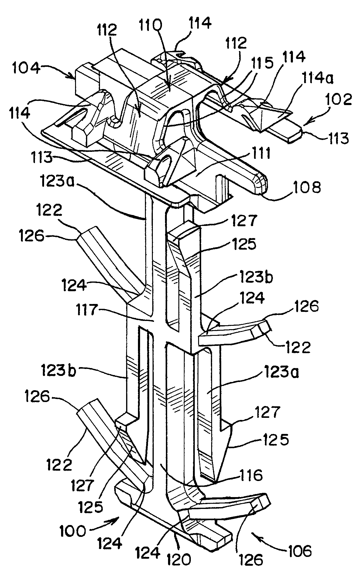
[0065]The preferred bar support 106 has four flexible arms 123 extending from the central hub 117 of the trunk 116 and alongside the trunk 116. These flexible arms 123 can be considered a first, second, third, and fourth flexible trunk members 121. In other embodiments, such as the embodiment 400 shown in FIGS. 20-21, two of the arms 423 are attached proximate the distal end 420 of the trunk 416, and two of the arms 423 are attached to the central hub 417. In any case, the arms 123 are preferably substantially parallel to the trunk 116, extending a short distance away from the trunk 116 and then angling sharply to run nearly parallel to the trunk 116. Two of the arms 123 point upward (i.e. away from the base 102), and two of the arms 123 point downward (i.e. toward the base 102). In one preferred embodiment (FIGS. 6-10), two of the arms 123 point toward one of the pairs of fingers 122, and the other two arms 123 point away from one of the pairs of fingers 122.
[0066]As may be seen in...
embodiment 300
[0083]A third preferred embodiment of a muntin clip according to the present invention is shown in FIGS. 18-19 and generally designated with the reference numeral 300. Each of the above described features, benefits, assembly and operation of the clip 100 shown in FIGS. 6-10 is applicable to the clip 300 of FIGS. 18-19, and is referred to using reference series 3xx, rather than 1xx. A difference between the clip 300 and the clip 100 shown in FIGS. 6-10 is in the arrangement of the arms 323. In the third clip embodiment 300, as described above, the flexible arms 323 of each set are located adjacent each other, rather than cater-corner. The set of arms 323a located closest to the base 302 have forward-facing projections 327, and the set of arms 323b located farthest from the base 302 have rearward-facing projections 327. Other components are substantially identical. It is understood when the clip 300 is inserted into the muntin bar 36, the arms 323a having the forward-facing projection...
embodiment 100
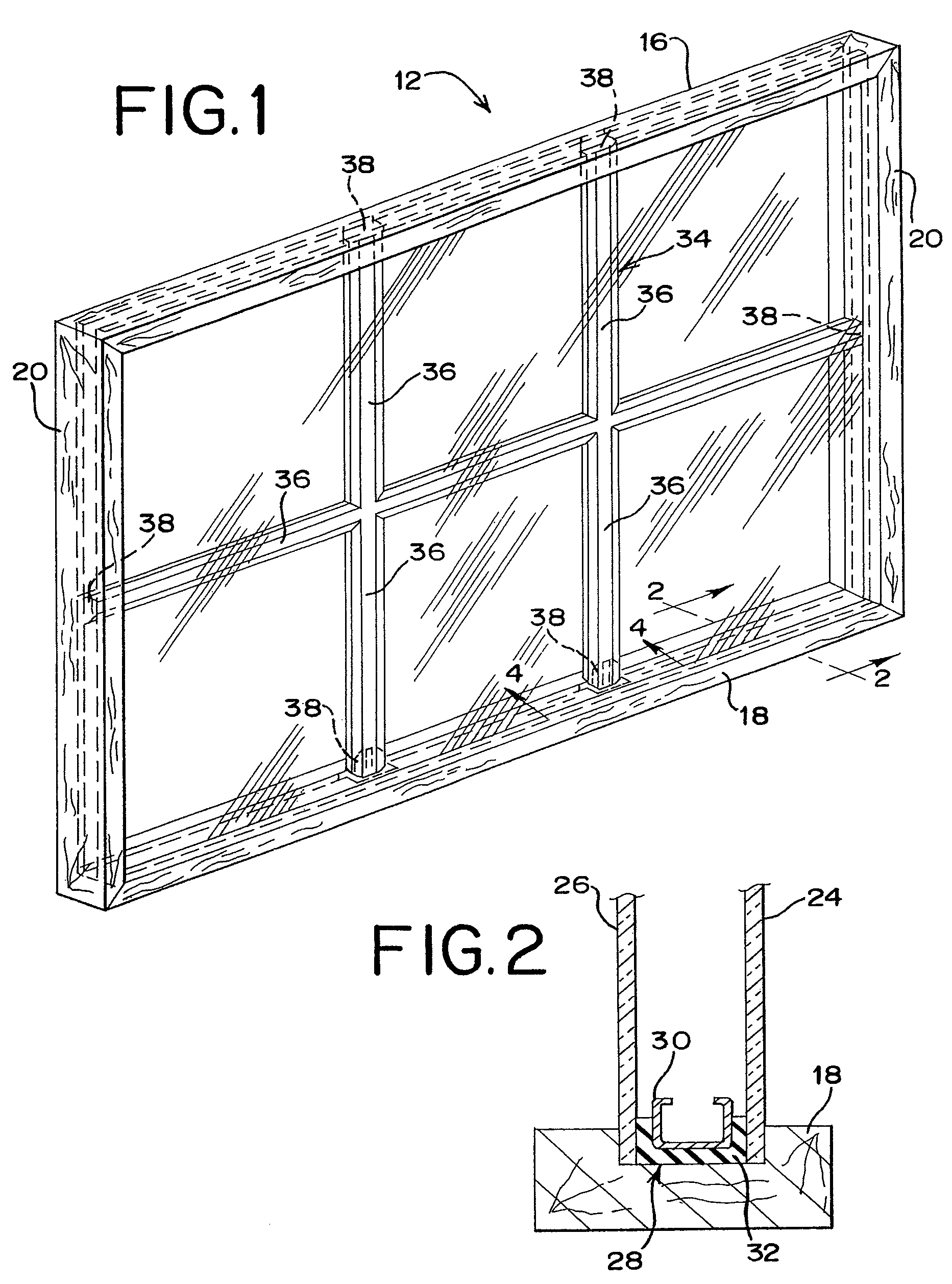
[0088]Each of the alternate embodiments of the clip 200, 300, 400, 500, 600, 700 is used and assembled with the muntin bar end 38 and spacer frame 30 in the manner described above with respect to the first clip embodiment 100.
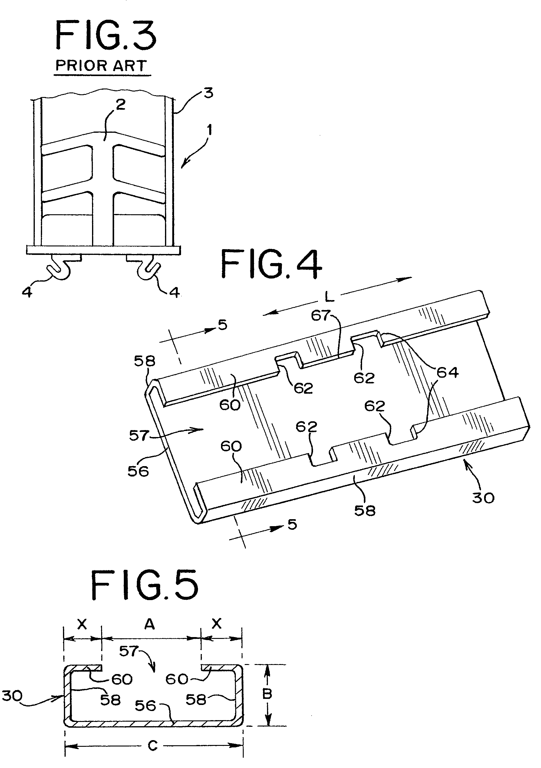
[0089]The flexible components of the bar support of the muntin clips described above permit a single clip to be connected to any of a variety of different muntin bars having a variety of different dimensions and configurations. Similarly, the flexible latch structure of the base permits a single clip to be connected to any of a variety of different spacer frames having a variety of different dimensions and configurations, and having openings of a variety of different widths. Thus, with the muntin clips as described above, the number of differently-sized muntin clips can be drastically reduced. This reduces inventory costs, additional tooling costs, and other costs associated with having to manufacture and store a large number of differently sized muntin clips. ...
PUM
 Abstract
Description
Claims
Application Information
 - R&D
- Intellectual Property
- Life Sciences
- Materials
- Tech Scout
- Unparalleled Data Quality
- Higher Quality Content
- 60% Fewer Hallucinations
Browse by: Latest US Patents, China's latest patents, Technical Efficacy Thesaurus, Application Domain, Technology Topic, Popular Technical Reports.
© 2025 PatSnap. All rights reserved.Legal|Privacy policy|Modern Slavery Act Transparency Statement|Sitemap|About US| Contact US: help@patsnap.com


